Check patentability & draft patents in minutes with Patsnap Eureka AI!

Key generation device, key derivation device, encryption device, decryption device, method and program

Active Publication Date: 2010-01-28
NEC CORP
View PDF1 Cites 12 Cited by
  • Summary
  • Abstract
  • Description
  • Claims
  • Application Information

AI Technical Summary

Benefits of technology

[0048]Solution to the problem in the conventional techniques can be achieved to some extent by employing the configuration wherein a strong hierarchical element which can calculate the image of the bilinear map with respect to the cyphertext is included in the public key. It is to be noted that qualification of “strong” is used here in the meaning of capability of calculating the bilinear map. Thus, in the present invention, by using members of G and the group that cannot provide the bilinear map with respect to the element of G, the elements that can provide the bilinear map with respect to the cyphertext c[1] and c[2] are employed as the secret to hierarchical element, and the secret hierarchical element is not included in the public key. In this way, the advantage that the identity to which the cy

Problems solved by technology

In addition, there is a tracing map φ, which is an isomorphic map capable of efficient calculation from G′ to G, and yet the reverse calculation of φ is difficult to achieve.
However, the conventional techniques cannot be used for this purpose.

Method used


Image

  • Key generation device, key derivation device, encryption device, decryption device, method and program
  • Key generation device, key derivation device, encryption device, decryption device, method and program
  • Key generation device, key derivation device, encryption device, decryption device, method and program

Examples


first embodiment

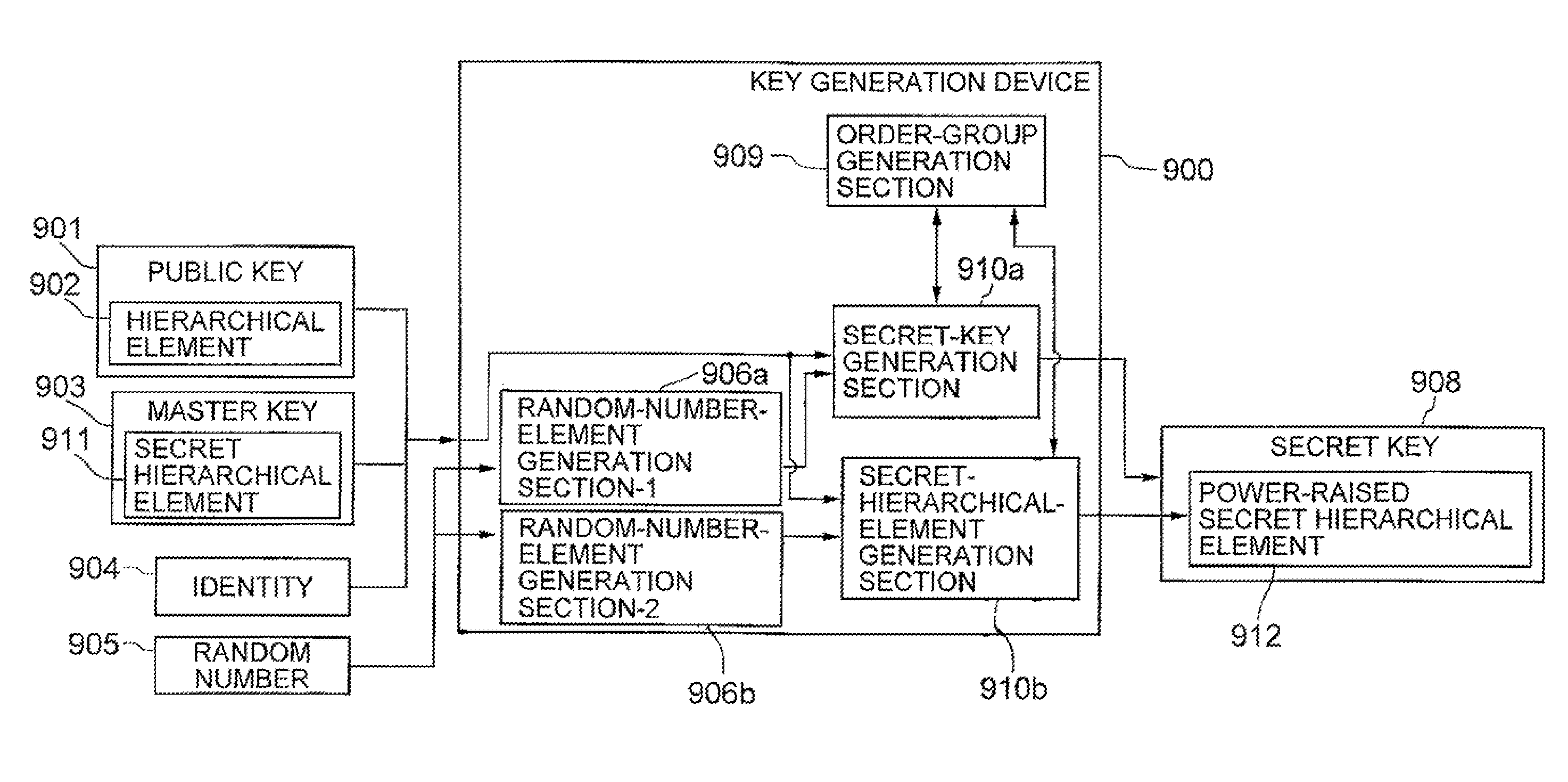
[0067]Hereinafter, embodiments of the present invention will be described in detail with reference to the drawings. FIG. 1 shows the configuration of a key generation device according to the present invention. The key generation device 900 includes an input unit, an output unit, to and a calculation unit (not shown). The calculation unit is configured by a program, and includes a random-number-element generation section-1 (906a), a random-number-element generation section-2 (906b), a secret-key generation section 910a, a secret-hierarchical-element generation section 910b, and an order-group generation section 909. The secret-key generation section 1010a and secret-hierarchical-element generation section 1010b issue a call to the order-group generation section when appropriate, and allow the same to generate an order group. Note that a portion of the program may be configured by a DSP (digital signal processor) in the present embodiment and subsequent embodiment. In addition, the ra...

second embodiment

[0078]to FIG. 5 shows the configuration of a key generation device according to the present invention. The key generation device 1300 includes an input unit, an output unit, and a calculation unit. The calculation unit is configured by a program, and includes a random-number-element generation section-1 (1306a), a random-number-element generation section-2 (1306b), a secret-key generation section 1310a, a secret-hierarchical-element generation section 1310b, and an order-group generation section 1309. The secret-key generation section 1310a and secret-hierarchical-element generation section 1310b issue a call to the order-group generation section 1309 when appropriate, and allow the same to generate the order group. A part of the program may be configured by a DSP (digital signal processor). The key generation device 1300 receives therein the public key 1301 (L, N, p, g′, g′[1], . . . , g′[N], g′[N+2], . . . , g′[2n], h[1], . . . , h[L], v, y), and master key 1303 (γ, v′, y′, (h′[1]...


PUM


Abstract

A key generation device (900) receives therein a public key (901) including a hierarchical element (902), a master key (903) including a secret hierarchical element (911), an identity θ (904), and a random number (905). The key generation device (900) generates two random number elements (906a, 906b) from the random number (905), and generates a secret key (908) including an element obtained by raising the secret hierarchical element (911) to a power of the two random numbers.

Description

TECHNICAL FIELD[0001]The present invention relates to a key generation device, a key derivation device, an encryption device and a decryption device. In particular, the present invention relates to a key generation device, a key derivation device, an encryption device, and a decryption device in an anonymous hierarchical-identity-based encryption system, a method and a program used in these devices.BACKGROUND ART[0002]A conventional anonymous hierarchical-identity-based encryption system will be described. It is defined in the following description that “p” is a prime number, “G” and “GT” are cyclic groups of an order “p”, and “e” is a non-degenerate bilinear map from G×G to G. Here, “being bilinear” means that e(gα, hβ)=e(g, g)αβ holds for all α, βεZ / pZ (Z is a set of integrals) and gεG. In addition, “being non-degenerate” means that e(g, g) is a constituent member of GT for the case where “g” is a constituent member of G. “L” represents the maximum depth of the hierarchical layers...

Claims


Application Information

Patent Timeline
IPC IPC(8): H04L9/08H04L9/00
CPCH04L2209/42H04L9/3073
Inventor FURUKAWA, JUN
Owner NEC CORP
Features
  • R&D
  • Intellectual Property
  • Life Sciences
  • Materials
  • Tech Scout
  • Unparalleled Data Quality
  • Higher Quality Content
  • 60% Fewer Hallucinations
Learn More