
Air Flow Control Method and System

Inactive Publication Date: 2010-02-04
COOL DYNAMICS REFRIGERATION
View PDF6 Cites 3 Cited by
  • Summary
  • Abstract
  • Description
  • Claims
  • Application Information

AI Technical Summary

Benefits of technology

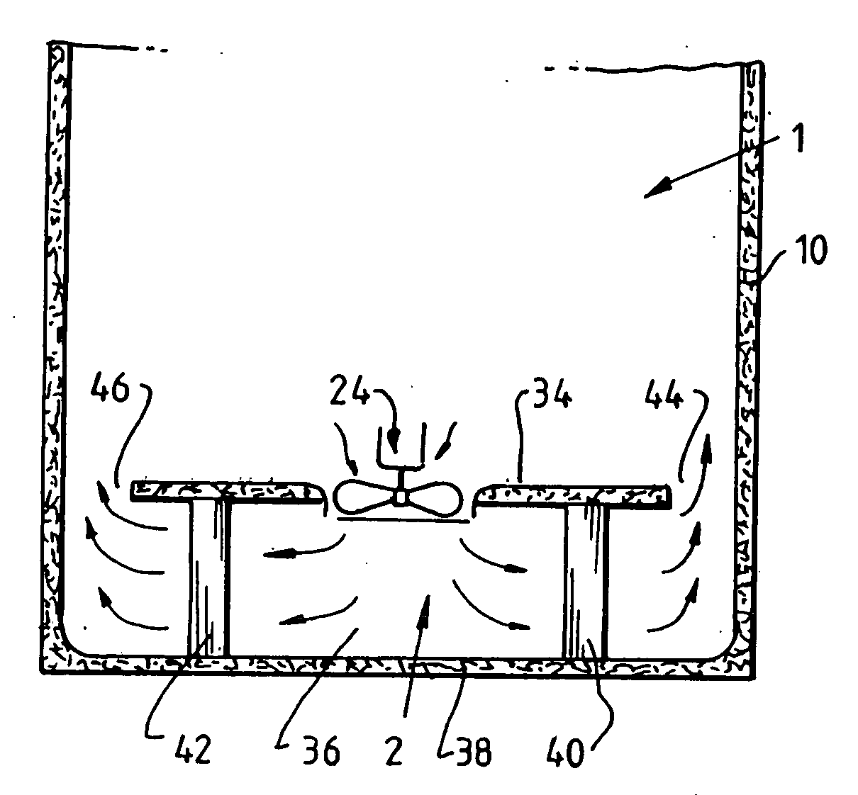
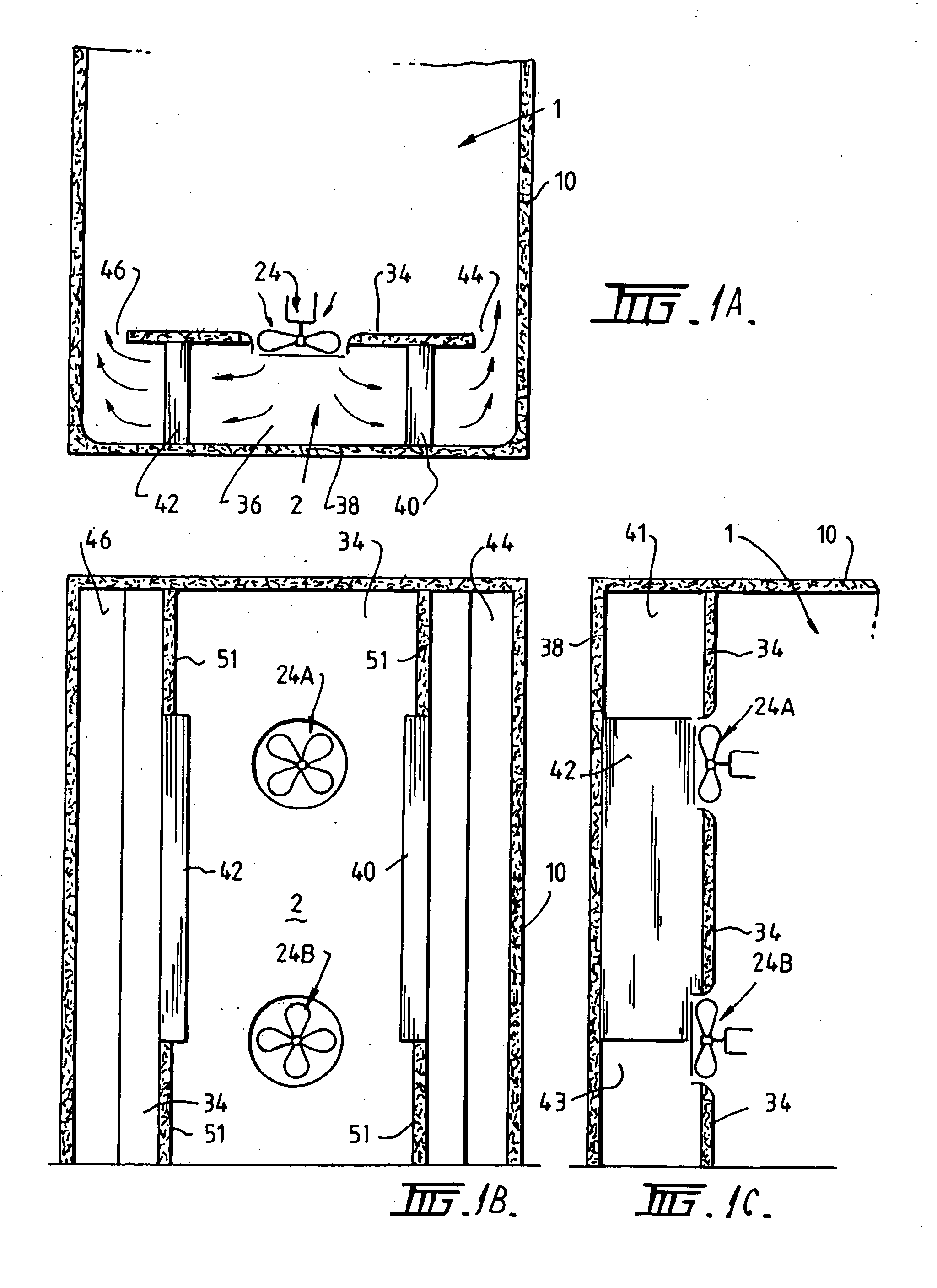
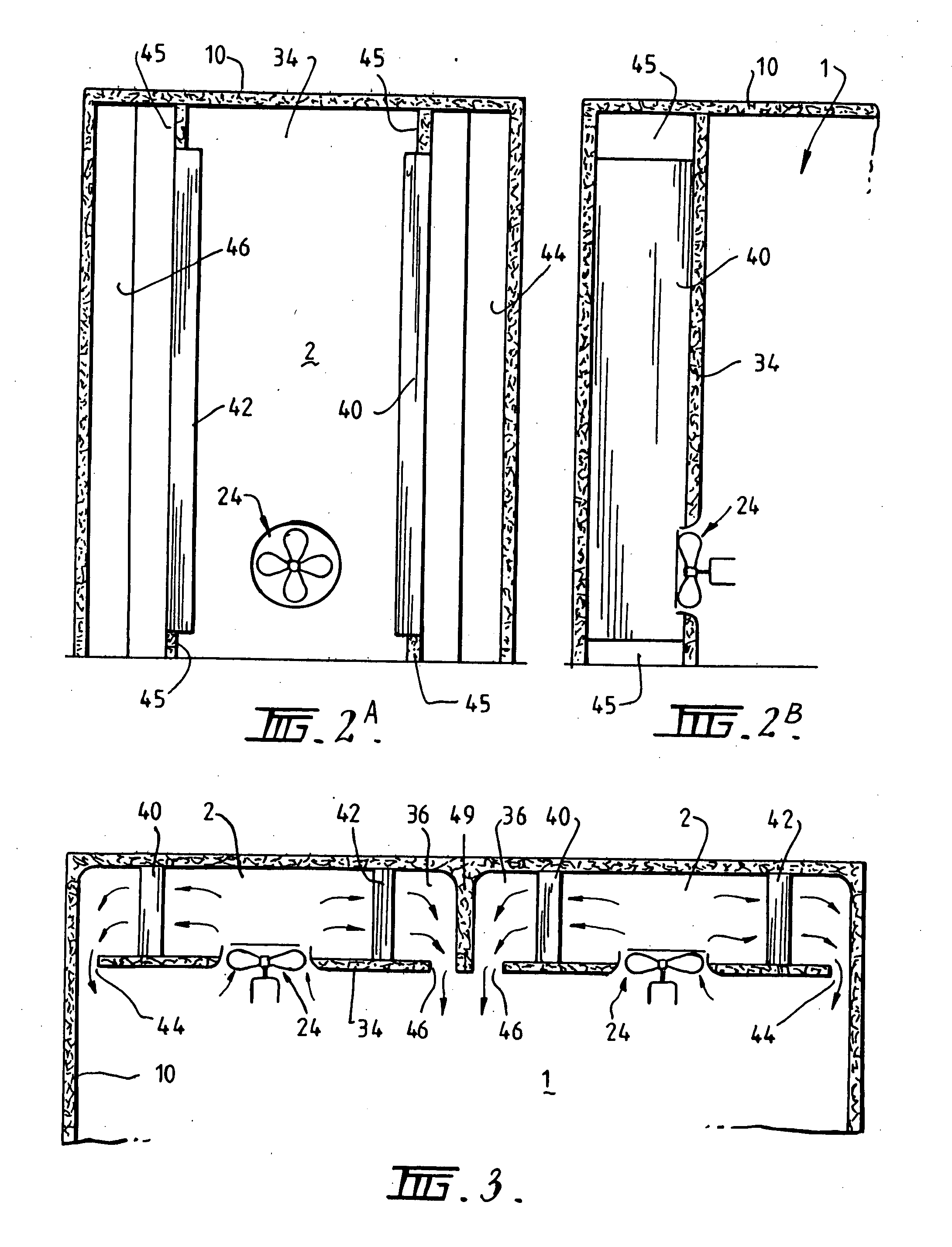
[0013]The zone containing the refrigeration coil means may be partitioned such that a refrigeration coil unit, an outlet and one or more extraction fans direct air from the produce storing zone through separate compartments for cooling and redirected through an outlet to cool a row of pallets storing the produce. In this way, the number of rows of pallets to be cooled can be controlled.

Problems solved by technology

With the position of such refrigeration coils, it has the disadvantage of having to allow for the height of the refrigeration coil unit which adds to the overall height of the cool room tiers, as a refrigeration coil unit is required for each tier.

Method used


Image

  • Air Flow Control Method and System
  • Air Flow Control Method and System
  • Air Flow Control Method and System

Examples


Embodiment Construction

[0049]Referring firstly to FIG. 1A, the invention can be seen to comprise an integrated air flow control facility for forced cooling of produce stored in a cool room 10. The air flow control facility is preferably integrated into the construction of the cool room 10 and comprises discrete and dedicated zones including a storage zone 1 for the storage of produce for cooling where the storage zone 1 generally forms the bulk of the cooling room. The air flow control facility also includes a dedicated and discrete refrigeration zone 2 formed as part of the cool room 10 but specifically separated from the storage zone 1 by virtue of a physical divider 34. The physical divider 34 is provided with one or more integral extraction fans 24 so as to provide for the drawing of air from the storage zone 1 into the refrigeration zone 2 for subsequent passage past refrigeration coil means 40 and 42 positioned within the refrigeration zone 2. The divider 34 further includes one or more outlets 44 a...


PUM


Abstract

An integrated airflow control facility for force cooling of produce in a cool room (10), including a dedicated storage zone (1) for storage of the produce and a dedicated refrigeration zone (2) separated by a physical divider (34) in which the divider includes one or more integral extraction fans (24) to extract air form the storage zone and direct said air through refrigeration coils (40 / 42) positioned in said the refrigeration zone for cooling thereof, in which the divider further includes one or more air outlets (44 / 46) to direct the cooled air exiting the refrigeration zone into the storage zone and in which the storage zone, refrigeration zone and the physical divider are integrated into a single airflow control facility.

Description

CROSS-REFERENCE TO RELATED APPLICATIONS [0001]The present application claims priority from Australian Provisional Patent Application No 2008903908 filed on 30 Jul. 2008, the content of which is incorporated herein by reference.FIELD OF THE INVENTION [0002]This invention relates to a method and system for air flow control and more particularly relates to a method and system for the control of air flow in cool rooms where a product is required to be force cooled.BACKGROUND OF THE INVENTION [0003]Produce, such as fruit and vegetables, are force cooled prior to storage and / or transportation. This type of cooling requires cool air to be drawn through the produce, which is usually contained within crates, boxes or cartons and can be stacked on one or more transportation pallets. The storage of the produce is such that it enables air to flow through the sides of the crates (or boxes or cartons) and thus, through the produce within that storage area.[0004]The produce is stacked on one or mo...

Claims


Application Information

Patent Timeline
IPC IPC(8): F25D17/06
CPCF25D17/005
Inventor GUYOMAR, DON
Owner COOL DYNAMICS REFRIGERATION
Learn More