Yarn twisting device for spinning

A technology of twisting and mounting boards, which is applied in the field of textile twisting devices, can solve the problems of different thicknesses of twisted threads, appearance and use of winding and winding, and small application range, so as to reduce the number of placements and maximize the benefits The effects of generalization and increased scope of application

Active Publication Date: 2021-02-09
ZHEJIANG MEILAIYA TEXTILE
View PDF5 Cites 2 Cited by
  • Summary
  • Abstract
  • Description
  • Claims
  • Application Information

AI Technical Summary

Problems solved by technology

[0004] Aiming at the deficiencies of the prior art, the present invention provides a twisting device for textiles, which solves the problem that only two strands of thread can be twisted, resulting in a small scope of application, and the different thickness of the thread after twisting affects the appearance, use, and final winding. The problem of entanglement

Method used


Image

  • Yarn twisting device for spinning
  • Yarn twisting device for spinning
  • Yarn twisting device for spinning

Examples


Embodiment 1

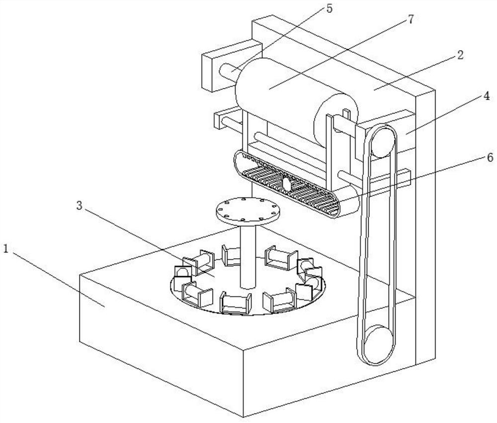
[0031] A twisting device for weaving, such as Figure 1-Figure 6 As shown, it includes a workbench 1, the rear of the workbench 1 is welded with a mounting plate 2, the inside of the workbench 1 is provided with a twisting mechanism 3, and the front of the mounting plate 2 is welded with two support plates 4, and the two support plates 4 are movably connected with a rotating shaft 5 , the surface of the rotating shaft 5 is movably connected with a winding drum 7 , and the front portion of the mounting plate 2 is provided with a winding mechanism 6 , and the winding mechanism 6 is located below the support plate 4 .

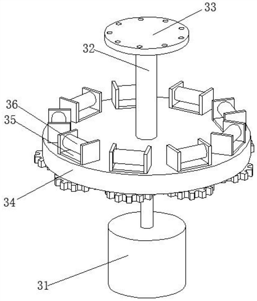
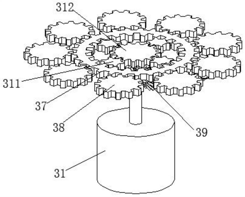
[0032] In this embodiment, the twisting mechanism 3 includes a motor 31, the output end of the motor 31 is clamped with a connecting shaft 32, the top of the connecting shaft 32 is welded with a fixed disk 33, and the surface of the connecting shaft 32 is welded with a rotating disk 34, and the surface of the connecting shaft 32 is welded with a rotating disk 34. ...

Embodiment 2

[0041] Such as Figure 6-Figure 7 As shown, on the basis of Embodiment 1, in this embodiment, the rear portion of the fixed plate 61 is welded and fixed to the front portion of the mounting plate 2, and the surfaces of the two moving plates 63 are in contact with the two ends of the winding drum 7 respectively. , the winding mechanism 6 is located above the twisting mechanism 3, which can move the twisted thread directly upwards for winding, without guiding to other planes for winding, which can reduce the setting of a guide wheel, reduce the cost, and reduce the cost. The friction of the guide wheel against the wire minimizes the risk of breakage due to friction.

[0042] It is worth noting that the adjustment device 64 includes a moving block 641, the inner wall of the moving block 641 is welded with teeth 642, the surface of the teeth 642 is meshed with a driving gear 643, and the axis of the driving gear 643 is welded with a transmission rod 644. The number of teeth of th...


PUM


Abstract

The invention relates to the technical field of spinning, and discloses a yarn twisting device for spinning. The yarn twisting device comprises a workbench, a mounting plate is welded to the rear partof the workbench, a yarn twisting mechanism is arranged in the workbench, two supporting plates are welded to the front part of the mounting plate, a rotating shaft is movably connected between the two supporting plates, a winding roller is movably connected with the surface of the rotating shaft, and a winding mechanism is arranged on the front part of the mounting plate. Multiple strands of yarns can rotate while twisting and rotating through the yarn twisting mechanism and the winding mechanism, so that each yarn is twisted when being wound tightly, the phenomenon of different thicknessesafter yarn twisting can be avoided, the appearance is beautified, and unqualified products are reduced; and nine strands of spinning yarns can be twisted at most at the same time, the application range of the yarn twisting device is widened, the twisted yarns are wound in a left-right reciprocating motion mode, and then the yarns are prevented from being wound in the winding process.

Description

technical field [0001] The invention relates to the technical field of textiles, in particular to a twisting device for textiles. Background technique [0002] The original meaning of textile is taken from the general term of spinning and weaving, but with the continuous development and improvement of the textile knowledge system and subject system, especially after the emergence of non-woven textile materials and three-dimensional composite weaving technologies, the current textile is not only a traditional Hand spinning and weaving also include garment, industrial and decorative textiles produced by non-woven technology, modern three-dimensional weaving technology, and modern electrostatic nano-netting technology. [0003] At present, the textile thread can only twist two strands when twisting, which is not practical for the production of multi-strand yarns. The scope of application is small, and the twisting may cause the thread itself to relax when it is rotated, resulti...

Claims


Application Information

Patent Timeline
Patent Type & Authority Applications(China)
IPC IPC(8): D01H7/00D01H1/36
CPCD01H7/00D01H1/36
Inventor 李显坤王荣军
Owner ZHEJIANG MEILAIYA TEXTILE
Why Eureka
Try Eureka