

Air-cooled wheel brakes
A technology of wheel brakes and wheels, applied in the direction of brakes, wheels, brake components, etc., can solve the problems of car crashes, tire wear, brake failure, etc., and achieve the effects of improving the air cooling effect, beautifying the appearance, and increasing costs
- Summary
- Abstract
- Description
- Claims
- Application Information
AI Technical Summary
Problems solved by technology
Method used
Image

Examples
Embodiment 1
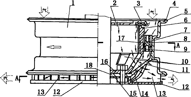
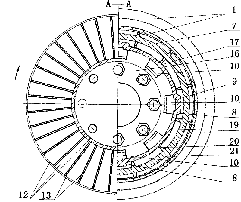
[0049] Such as figure 1 figure 2 image 3 Figure 4 Figure 5 Figure 6 Figure 7 Figure 8 Figure 9 Figure 10 Figure 11 As shown, the air-cooled wheel brake mainly includes: the impeller device wheel, the airflow adjustment device, and the brake set on the same axis. figure 1 figure 2 Among them, the impeller device is outside the spoke 14 of the wheel, the rim 1, and the bead seat 5, and the blade 13 is suitable for the shape of the above-mentioned rim 1.
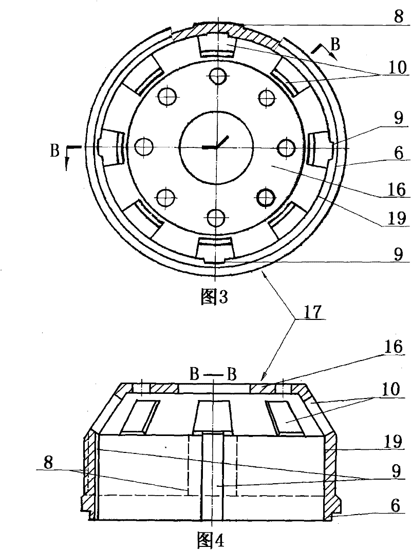
[0050] exist figure 1 image 3 Figure 4 Figure 5 Among them, the brake is composed of the brake drum 17 in the drum brake shown, the brake base plate 3 and the brake shoe 22, the drum-shaped brake drum 17 and the brake base plate 3 form a coaxial space, the brake drum An air intake gap of more than 0.5 mm or an air intake annular gap of 0.5 mm to 18 mm is set between the mouth 6 and the 3 sides of the brake bottom plate, and an air outlet is set within the brake drum bottom 16 and / or the inner barrel...
Embodiment 1A
[0055] The airflow adjustment device is the airflow rate ring 27 and the airflow expansion and contraction ring 32 . Air velocity ring 27 (such as Figure 6 Figure 7 Shown), is made up of ring skeleton 7, inner support 20 and outer support 21, and ring skeleton 7 is the annular body of a short pipe or the double pipe body that cross section is H shape, is made respectively in the inner circle or the outer circle of pipe annular body There is an inner support 20 and an outer support 21, and the inner support 20 and / or the outer support 4 are respectively composed of a plurality of straight strips or curved strips or spiral plates or inclined plates or columns. When the annular space between the inner circle of the rim 1 and the brake is too large and the air flow is too slow, install the air velocity ring 27 into the annular space to reduce the windward area and accelerate the air flow speed, so that the air can quickly flow through the inner bracket 20 and The gap of the ou...
Embodiment 1B
[0057] exist Figure 8 Figure 9 Among them, the airflow expansion and contraction ring 32 is composed of a plurality of trapezoidal shrapnel 29, a ring bracket 31, a column 28, and a support ring 30. The shrapnel 29 is a fan-shaped or trapezoidal shrapnel. The conical tubular shape of the ring bracket 31 is connected and supported with the column 28, and the main column 28 is tubular or column-shaped and is seated and connected on the support ring 30. The support ring 30 is circular and supported by the inner circular wall of the rim. Under the action of air stamping and rotating centrifugation, the junction of the upper end of the shrapnel 29 and the annular support 31 swings in a circle, changing the area through which the air passes.
[0058] Such as figure 1 Figure 10 Figure 11 As shown, the large disc impeller 50 is made up of the impeller connecting disc 15, the blade 13, and the cover plate 12. The impeller connecting disc 15 and the cover plate 12 are an integra...
PUM
 Abstract
Description
Claims
Application Information