
Method for cladding and molding mobile internet device antenna by employing out-mold decoration

A technology of mobile Internet and high-voltage transfer printing, which is applied to the antenna support/installation device, the structural form of the radiating unit, the structural form of the radiating element, etc., and can solve problems such as warping and uneven joints, insufficient bonding force, and holes.

Inactive Publication Date: 2012-08-01
QINGDAO LONGBOW TECH
View PDF0 Cites 11 Cited by
  • Summary
  • Abstract
  • Description
  • Claims
  • Application Information

AI Technical Summary

Problems solved by technology

Therefore, if the antenna is made by two-shot molding method or laser activation method (LDS), holes will be formed on the surface of the substrate, which will affect the view.
[0006] In addition, if the two-shot molding method is used, it is easy to produce a gap at the junction of the two injections, or the bonding force is insufficient, which may easily cause the surface of the substrate to be uneven, or during the use of the part, it may also be due to external force factors or the workpiece itself. Internal stress causes warping and unevenness at the junction of the two injections, which affects the characteristics and appearance of the antenna

Method used


Image

  • Method for cladding and molding mobile internet device antenna by employing out-mold decoration
  • Method for cladding and molding mobile internet device antenna by employing out-mold decoration
  • Method for cladding and molding mobile internet device antenna by employing out-mold decoration

Examples


Embodiment Construction

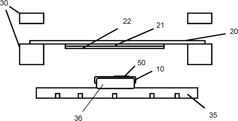
[0033] Take a MID substrate 10 and a film 20 (preferably a plastic film); wherein the MID substrate 10 is generally a plastic injection part, and a metal layer 50 has been formed thereon, and the metal layer 50 is an antenna circuit; The film 20 can be plain, or printed with a pattern 21 and coated with an adhesive material 22 . The film 20 is clamped on a holder 30, and the MID substrate 10 is placed on a positioning support jig 36, and the positioning support jig 36 is installed on a base 35 ( figure 1 );

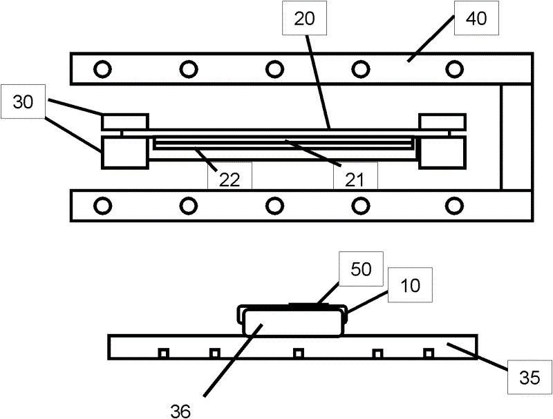
[0034] Then heat and soften the film 20 with the heater 40 ( figure 2 ).

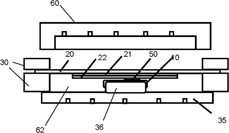
[0035] Then remove the heater 40, cover the holder 30 together with the film 20 on the top of the MID substrate 10, and after the holder 30 and the base 35 are closed, form a lower cavity 62 below the film 20 ( image 3 ).

[0036] First, the lower cavity 62 is evacuated, then an isolation cavity 60 and the holder 30 are closed, and an upper cavity 61 is formed above the film 20, and then high...


PUM


Abstract

The invention provides a method for cladding and molding a mobile internet device (MID) antenna by employing out-mold decoration (OMD). The method comprises the following steps: taking an MID substrate and a plastic film, wherein an antenna circuit has been formed on the MID substrate; clampedly arranging the plastic film on a clamping pedestal and heating the film by utilizing a heater; covering the film above the MID substrate; and employing high pressure air to enable the film to be pressed and tightly attached above the MID substrate. according to the invention, the OMD technology is employed; and the plastic film is covered on the MID substrate; the film not only can improve and beautify the substrate surface but also can protect an antenna on the substrate from being damaged, thereby prolonging the service life of the antenna.

Description

technical field [0001] The field of the invention is a process related to antennas for mobile devices, in particular a method of overmolding mobile internet device (MID) antennas using high voltage transfer printing (OMD). Background technique [0002] Due to the vigorous development of information technology, the advancement of wireless communication technology has been driven, and mobile devices have become an essential communication tool for modern people. Therefore, the demand for mobile phone functions is also increasing day by day. Since the radio waves of wireless communication must be up-frequency and carried by the carrier, they can be effectively multiplexed and transmitted, so these actions must be performed with the help of an antenna. Therefore, the antenna is a very important element in the wireless communication equipment. Traditional antennas are mainly external antennas, such as helical antennas or dipole antennas. It's just that the antennas of these sty...

Claims


Application Information

Patent Timeline
Patent Type & Authority Applications(China)
IPC IPC(8): H01Q1/38H01Q1/40H01Q1/22
Inventor 尹承辉王胜弘胡士豪胡健华
Owner QINGDAO LONGBOW TECH
Learn More