Fuel tank vent including a membrane separator

a technology of membrane separator and fuel tank, which is applied in the direction of space heating and ventilation details, propulsion parts, domestic heating, etc., can solve the problems of high cost of metal separator vent, metal can quickly become saturated with fuel, and the cost associated with it is not economical for small engine systems

Inactive Publication Date: 2010-02-04
GENERAL ELECTRIC CO
View PDF18 Cites 35 Cited by
  • Summary
  • Abstract
  • Description
  • Claims
  • Application Information

AI Technical Summary

Problems solved by technology

If the liquid fuel comes in contact with the porous metal, the metal can quickly become saturated with the fuel.
Moreover, the porous metal separator vent is generally comprised of an expensive metal.
The cost associated therewith is not economical for small engine systems, such as lawn mowers, power saws, and the like.

Method used


Image

  • Fuel tank vent including a membrane separator
  • Fuel tank vent including a membrane separator
  • Fuel tank vent including a membrane separator

Examples


Embodiment Construction

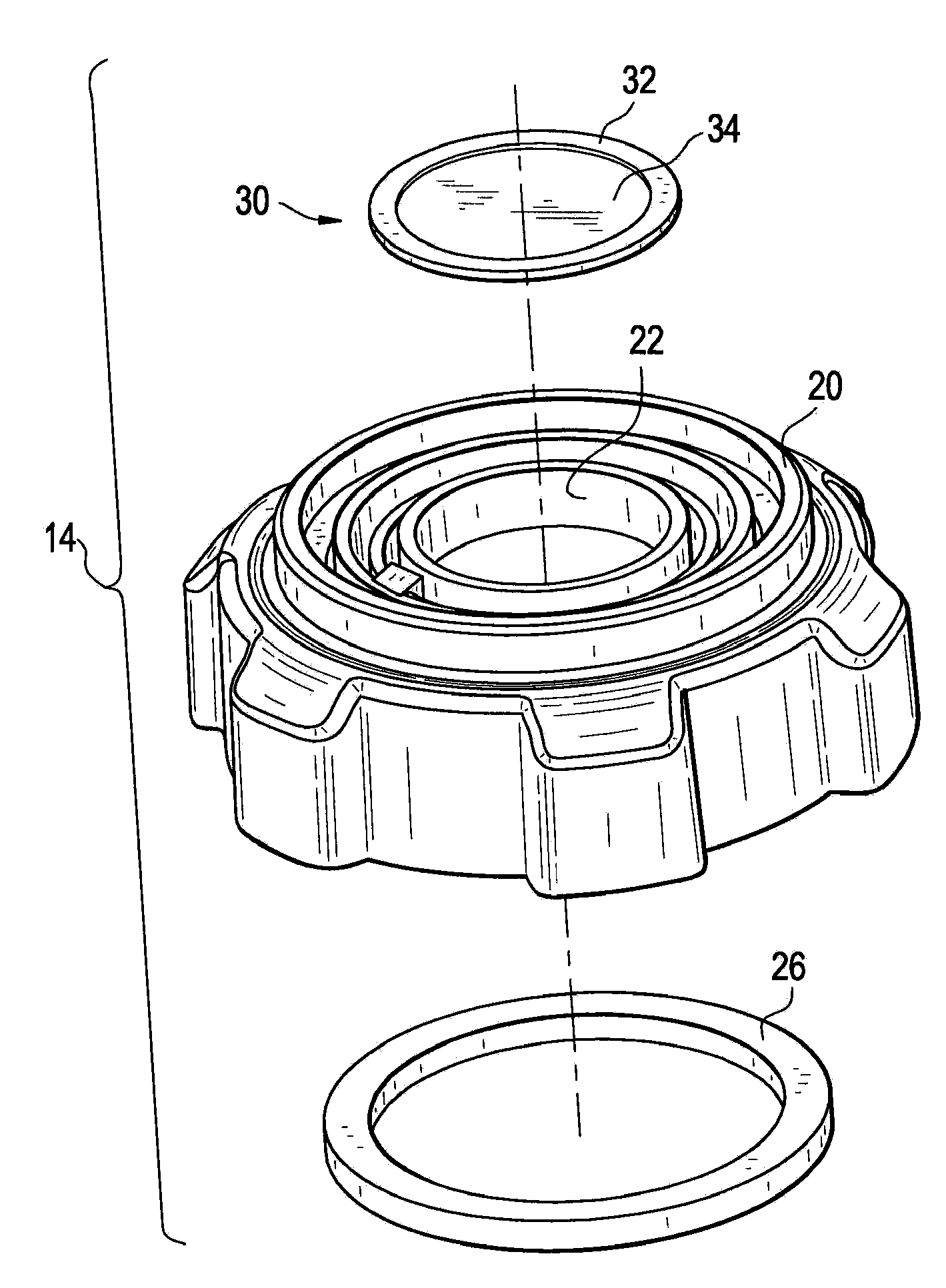
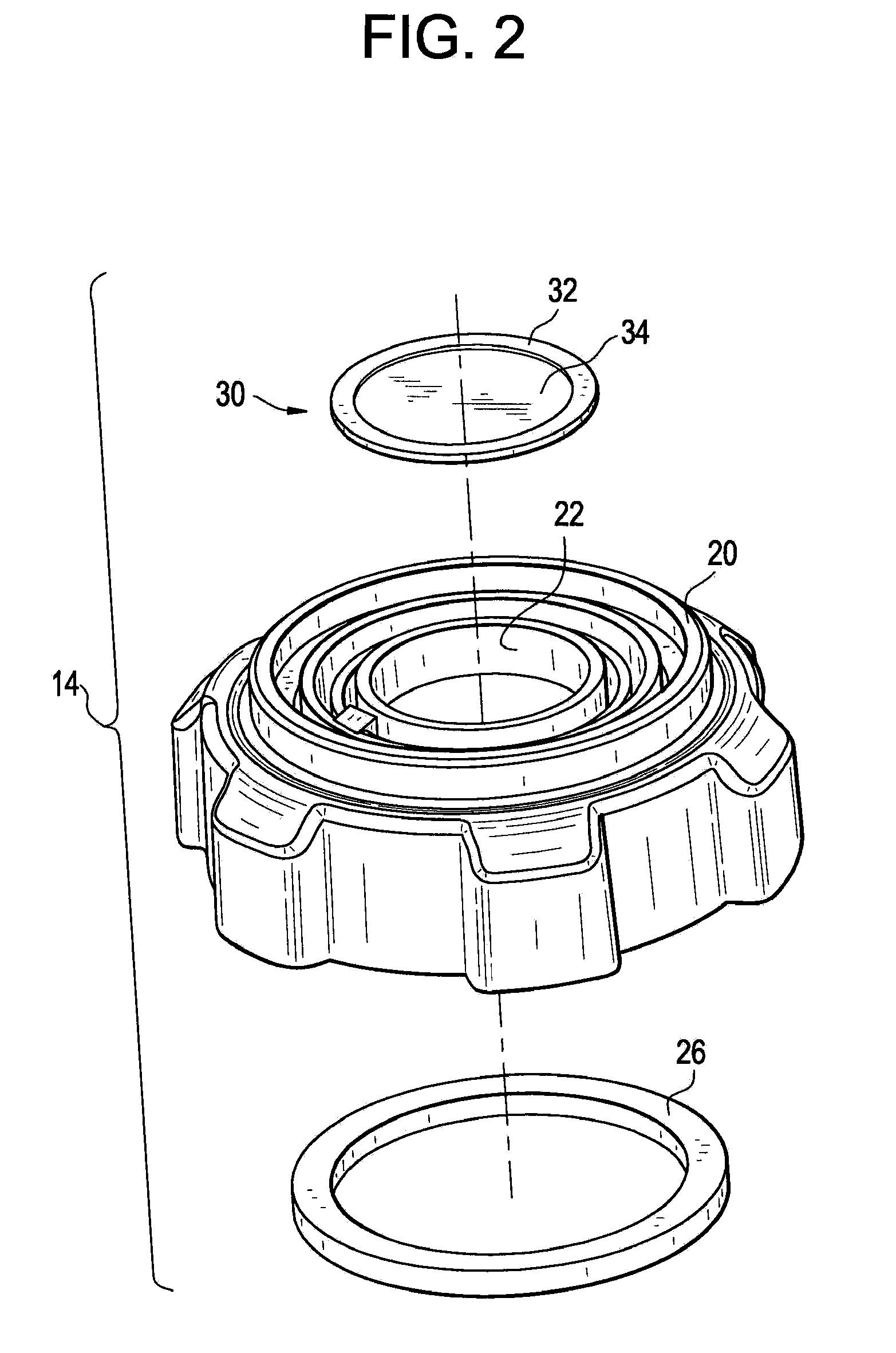
[0015]The fuel tank vents and vent systems described herein include an oleophobically-treated nanoporous membrane separator. As used herein, the term “nanoporous” refers to a membrane separator having a mean pore size of about 0.1 nanometers (nm) to about 50 nm. The oleophobic treatment on the membrane separator can increase the fuel repellency of the membrane separator and allow the fuel tank vent to be effective even as a roll-over vent in small engine applications. The oleophobic treatment, moreover, can increase the operating life of the membrane separator by helping to prevent the overloading or saturation of the vent by the liquid fuel, particularly when the engine tips over. The treatment prevents saturation of the membrane, thereby allowing vapor / air to pass and preventing the liquid fuel through, even when the fuel is in direct contact with the membrane. The nanoporous membrane separator as described herein comprises materials that are advantageously less expensive than the...


PUM

PropertyMeasurementUnit
mean pore sizeaaaaaaaaaa
pore sizeaaaaaaaaaa
pore sizeaaaaaaaaaa

Abstract

A fuel tank vent includes a nanoporous membrane separator positioned in an opening in a fuel tank to allow vapor from a fuel to flow across a membrane, wherein the membrane comprises a network in which surfaces of the network define a plurality of interconnecting pores extending through the membrane, wherein the plurality of interconnecting pores have a mean pore size of about 0.1 nanometers to about 50 nanometers, and are permeable to a selected one or both of the fuel vapor and air, and impermeable to a liquid fuel; and an oleophobic enhancement coating disposed on surfaces of the plurality of interconnecting pores and configured to provide oleophobicity to the membrane.

Description

BACKGROUND OF THE INVENTION[0001]The present disclosure relates generally to a vent for the fuel tanks of internal combustion engines and, more specifically, to fuel tank vents having an oleophobically-treated membrane separator.[0002]Combustion engines, such as small internal combustion engines,, and the like for machines, such as lawn mowers, garden tractors, power saws, power generators, and the like, generally require a fuel tank for their operation. The fuels used; such as ethanol, methanol, gasoline, diesel fuel, kerosene, and the like, naturally have, under standard conditions, a high vapor pressure. Fuel vapors, increased by mixing of the liquid fuel or by warming thereof, can be formed in the tank systems. The fuel vapors can exert a pressure on the tank systems and the fuel system. Appropriate pressure compensations are therefore desired for the tank and fuel systems.[0003]Pressure compensation can be achieved by venting of the tank and / or fuel system. A vent to the atmosp...

Claims


Application Information

Patent Timeline
Patent Type & Authority Applications(United States)
IPC IPC(8): B01D53/22F16K24/04B65D25/38
CPCB01D67/0088B01D2325/02B60K2015/03276B60K15/03504B01D2325/38Y10T137/3084Y10T137/86324B01D71/00B01D71/16B60K15/035
Inventor BANSAL, VISHALFARZANA, NUSRAT
Owner GENERAL ELECTRIC CO
Why Eureka
Try Eureka