Pneumatic radial tire

Active Publication Date: 2010-02-04
YOKOHAMA RUBBER CO LTD
View PDF8 Cites 5 Cited by
  • Summary
  • Abstract
  • Description
  • Claims
  • Application Information

AI Technical Summary

Benefits of technology

[0006]The inventors of the present invention conducted an earnest study, based on durability tests, on a pneumatic radial tire including at least two cross belt layers which are disposed on an outer circumferential side of the carcass layer in a tread portion, and at least one circumferential-direction reinforcement layer disposed between these cross belt layers, the width of the circumferential-direction reinforcement layer being smaller than that of each cross belt layer. It was observed that the cords in each edge portion of the circumferential-direction reinforcement layer tend to break. With this taken into consideration, the inventors have found an optimal structure for suppressing fatigue break of each edge portion of the circumferential-direction reinforcement layer, and developed the findings into the present invention.
[0007]In the present invention, the circumferential-direction reinforcement layer includes the steel cords of the two types which differ in elongation at break. The steel cord having relatively small elongation at break is disposed in the center portion of the circumferential-direction reinforcement layer, whereas the steel cord having relatively large elongation at break is disposed in each of the outer side portions of the circumferential-direction reinforcement layer. By this, the present invention enables a width increase for the circumferential-direction reinforcement layer, as well as suppression of fatigue break of the edge portions of the circumferential-direction reinforcement layer. Consequently, the present invention makes it possible to enhance the effect of improving the high-speed durability of the tire on the basis of the circumferential-direction reinforcement layer. Furthermore, the cross belt layers are separated away from each other at the outer sides respectively of end positions, in the width direction, of the circumferential-direction reinforcement layer. With this separation, the present invention is capable of reducing the shear strain in each edge portion of the cross belt layers, and is thus capable of suppressing the separation in the edge portion. Thereby, the present invention makes it possible to improve the load durability of the tire.
[0008]In the present invention, it is desirable that each steel cord disposed in the center portion of the circumferential-direction reinforcement layer should have an m×n structure where the direction of the first twist of filaments of the steel cord coincides with the direction of the second twist of the filaments, the elongation at break of the steel cord being 3% or more. In addition, it is desirable that the steel cord disposed in each of the outer side portions of the circumferential-direction reinforcement layer should have filaments which are preformed into a zigzag shape, and the elongation at break of the steel cord is 6% or more. In particular, it is desirable that the difference between the elongation at break of the steel cord disposed in each of the outer side portions of the circumferential-direction reinforcement layer and the elongation at break of the steel cord disposed in the center portion of the circumferential-direction reinforcement layer should be 1.5% or more. Moreover, it is desirable that the ratio of the total width of the circumferential-direction reinforcement layer to the maximum width of the cross belt layers should be 65% to 95%. It is desirable that the ratio of the width of the center portion of the circumferential-direction reinforcement layer to the total width of the circumferential-direction reinforcement layer should be 40% to 85%. When these conditions are satisfied, the present invention is capable of achieving the high-speed durability and load durability of the tire at the same time, at high levels.
[0009]The present invention can be applied to various pneumatic radial tires. It is desirable that the present invention should be applied to pneumatic radial tires each with an aspect ratio of 60% or less. In particular in a case where the present invention is applied to heavy-duty pneumatic radial tires, the present invention brings about a remarkable operation and effect.

Problems solved by technology

For this reason, the cords in each edge portion of the circumferential-direction reinforcement layer tend to break due to their fatigue.
However, in the case where the cross belt layers are formed larger in width than the circumferential-direction reinforcement layer, and where such cross belt layers are laminated to be in direct contact with each other at outer sides, in the width direction, of the circumferential-direction reinforcement layer, the total width of the circumferential-direction reinforcement layer is restricted.
As a result, the circumferential-direction reinforcement layer does not always bring a sufficient effect of improving the high-speed durability of the tire.

Method used


Image

  • Pneumatic radial tire
  • Pneumatic radial tire
  • Pneumatic radial tire

Examples


examples

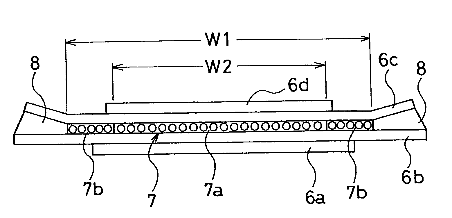
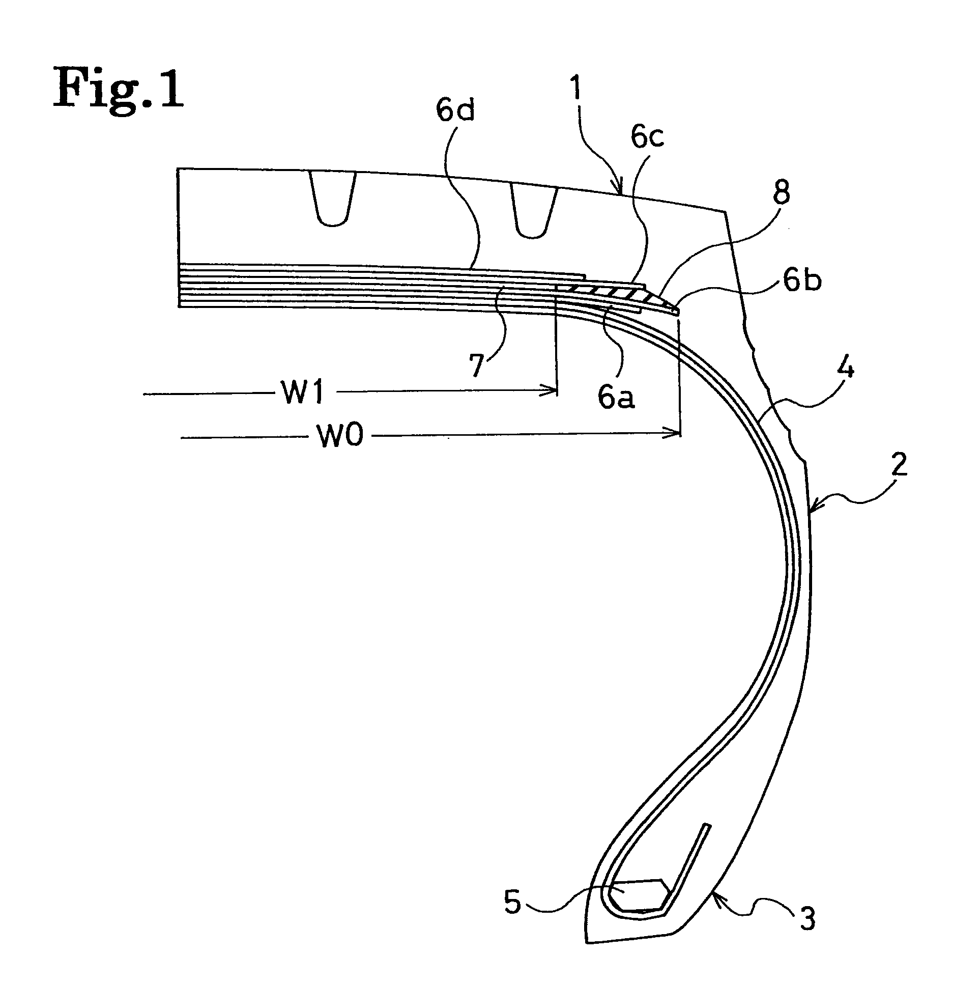
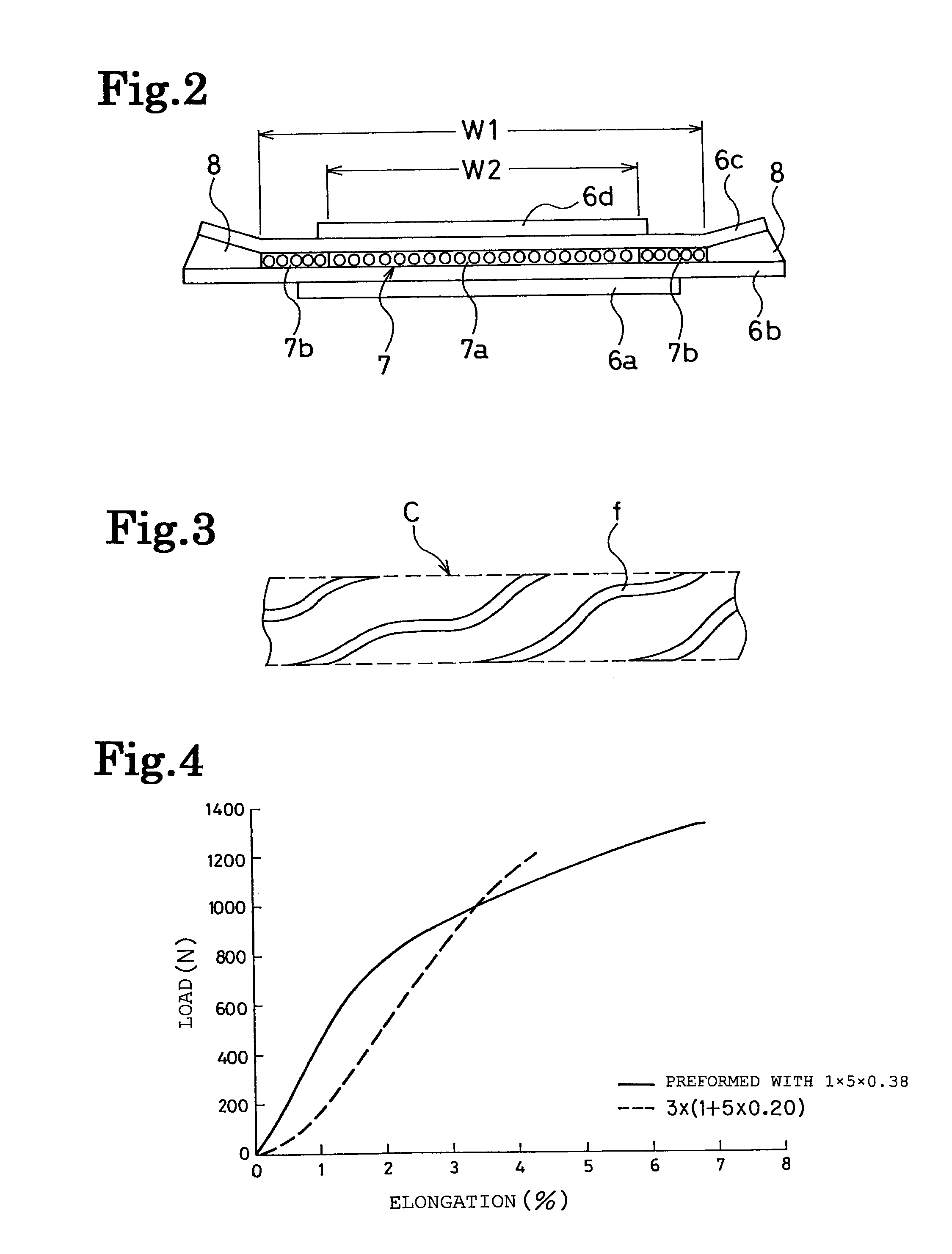
[0040]For each of Examples 1 to 4, a pneumatic radial tire was produced with the following specification. The tire size was 435 / 45R22.5. Two cross belt layers were disposed on the outer circumferential side of the carcass layer in the tread portion. One circumferential-direction reinforcement layer was disposed between these cross belt layers, and the width of the circumferential-direction reinforcement layer was smaller than the width of each of the cross belt layers. The cross belt layers were separated away from each other at the outer sides of the respective end positions, in the width direction, of the circumferential-direction reinforcement layer. The circumferential-direction reinforcement layer was configured of steel cords of two types which differ in elongation at break. The steel cords having relatively small elongation at break were disposed in the center portion of the circumferential-direction reinforcement layer, whereas the steel cords having relatively large elongat...


PUM

PropertyMeasurementUnit
Fractionaaaaaaaaaa
Fractionaaaaaaaaaa
Fractionaaaaaaaaaa

Abstract

Provided is a pneumatic radial tire: that includes a circumferential-direction reinforcement layer having a width increased with fatigue break of the circumferential-direction reinforcement layer being suppressed at edge portions thereof; and that suppresses separation in each of cross belt layers at edge portions thereof. A pneumatic radial tire according to the present invention is a pneumatic tire including: at least two cross belt layers disposed on an outer circumferential side of a carcass layer in a tread portion; and at least one circumferential-direction reinforcement layer disposed between these cross belt layers, a width of the circumferential-direction reinforcement layer being smaller than that of each cross belt layer. The pneumatic radial tire is configured so that: the cross belt layers are separated away from each other at outer sides respectively of end positions, in a width direction, of the circumferential-direction reinforcement layer; the circumferential-direction reinforcement layer includes steel cords of two types which differ in elongation at break; and the steel cord having relatively small elongation at break is disposed in a center portion of the circumferential-direction reinforcement layer, whereas the steel cord having relatively large elongation at break is disposed in each of outer side portions of the circumferential-direction reinforcement layer.

Description

TECHNICAL FIELD[0001]The present invention relates to a pneumatic radial tire with an aspect ratio of 60% or less, which is suitable as a heavy-duty tire. Specifically, the present invention relates to a pneumatic radial tire: that includes a circumferential-direction reinforcement layer having a width increased with fatigue break of the circumferential-direction reinforcement layer being suppressed at edge portions thereof; and that suppresses separation in each of cross belt layers at edge portions thereof.BACKGROUND ART[0002]These years, a growing number of trucks and buses use heavy-duty tires that employ a single tire installation with a low-profile structure for the purpose of reducing fuel consumption and saving natural resources. The most widely employed practice for tires each with an aspect ratio of 60% or less is to dispose a circumferential-direction reinforcement layer, whose cord angle to the circumferential direction of the tire is substantially 0 degrees, between cro...

Claims


Application Information

Patent Timeline
IPC IPC(8): B60C9/22
CPCB60C9/2006B60C9/22B60C2009/2029B60C9/185B60C2009/2223B60C2200/06
Inventor HARIKAE, SHINYA
Owner YOKOHAMA RUBBER CO LTD
Why Eureka
Try Eureka