Paper width detection method for a label printer, printing control method for a label printer, and a label printer

a detection method and label printer technology, applied in printing, typewriters, other printing apparatus, etc., can solve the problems of low light that is reflected back by the liner, detection errors, and difficult detection of the point where the reflectivity changes near the edge of the liner, so as to achieve the effect of determining the paper width of a recording medium more accurately

Inactive Publication Date: 2010-02-04
SEIKO EPSON CORP
View PDF1 Cites 24 Cited by
  • Summary
  • Abstract
  • Description
  • Claims
  • Application Information

AI Technical Summary

Benefits of technology

[0011]A first object of the present invention is to provide a label printer and a paper width detection method for a label printer that can determine the paper width of a recording medium more accurately than the related art using a paper width detector.

Problems solved by technology

Methods that detect the recording medium width based on change in the reflectivity or transmittance when scanning across the width of the recording medium cannot differentiate the change in reflectivity or change in transmittance caused by punch holes, soiling, or damage to the recording medium from a change in reflectivity or change in transmittance at the edge of the recording medium, and can therefore result in detection errors.
Furthermore, because the amount of light that is reflected back by the liner is low when the recording medium uses a transparent liner or a liner with low reflectivity, such as a black liner, the point where the reflectivity changes near the edge of the liner can be difficult to detect.
The change in transmittance near the edge of the liner can also be difficult to detect with a recording medium that has a liner with high transmittance, such as a transparent liner.
Erroneous detection or a detection error reporting that the edge of the recording medium could not be detected may therefore result.
If the label paper has the labels affixed to a liner for which the edges can be difficult to detect, the likelihood of being able to detect at least the width of the labels is high if the paper width detection process is executed when the labels are at the paper width detection position.
However, if the paper width is detected when the gap between labels (the portion of the liner between adjacent labels) is at the paper width detection position, the edges of the liner and the edges of the label cannot be detected, and an error reporting that the paper width could not be detected may result.
The likelihood of such detection errors is particularly high with die-cut label paper when the labels are affixed to a liner for which detecting the edges can be difficult, such as a transparent liner or black liner.
Therefore, even if the recording medium uses a liner that is difficult for the paper width detector to detect the edges of, the possibility of being able to detect at least the width of the labels is high.
The error of being unable to detect the paper width (a paper width detection failure) therefore does not occur easily.
However, because there will always be a location farther to the left or the right of such soiling or damage where the output value changes due to an edge of the recording medium, the likelihood of the method of the embodiment of the invention mistakenly identifying the position of such soiling, damage, or die-cut marks as the position of the left or right edge of the recording medium is low.
However, because the changes in the output value at the edges of the liner are closer to the edges of the scanning area than such die-cut marks, the likelihood of mistakenly recognizing such die-cut process marks as the left or right edge of the recording medium is low.

Method used


Image

  • Paper width detection method for a label printer, printing control method for a label printer, and a label printer
  • Paper width detection method for a label printer, printing control method for a label printer, and a label printer
  • Paper width detection method for a label printer, printing control method for a label printer, and a label printer

Examples


Embodiment Construction

[0042]A label printer and a paper width detection method for the label printer according to preferred embodiments of the present invention are described below with reference to FIG. 1 to FIG. 8.

General Configuration

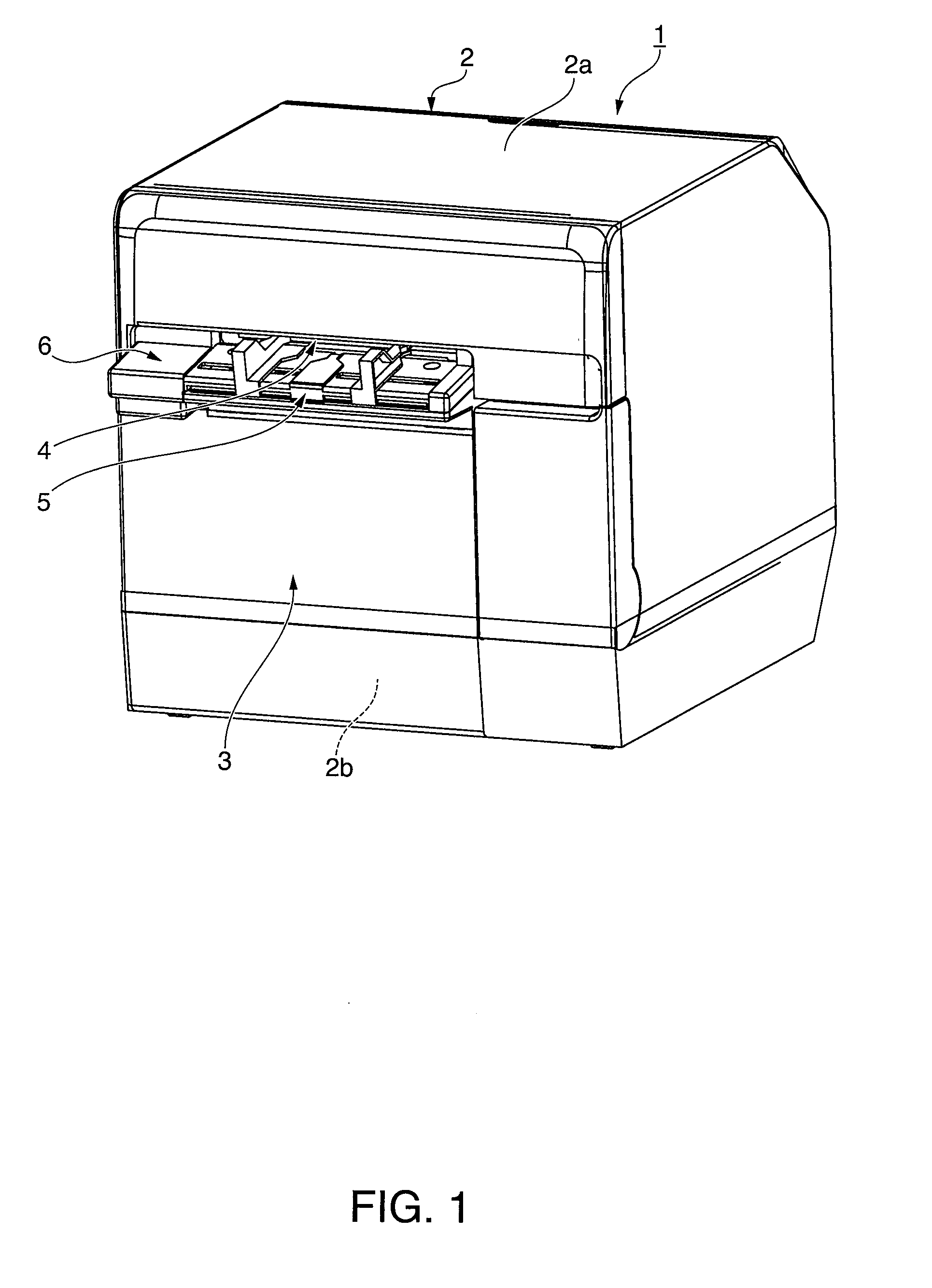
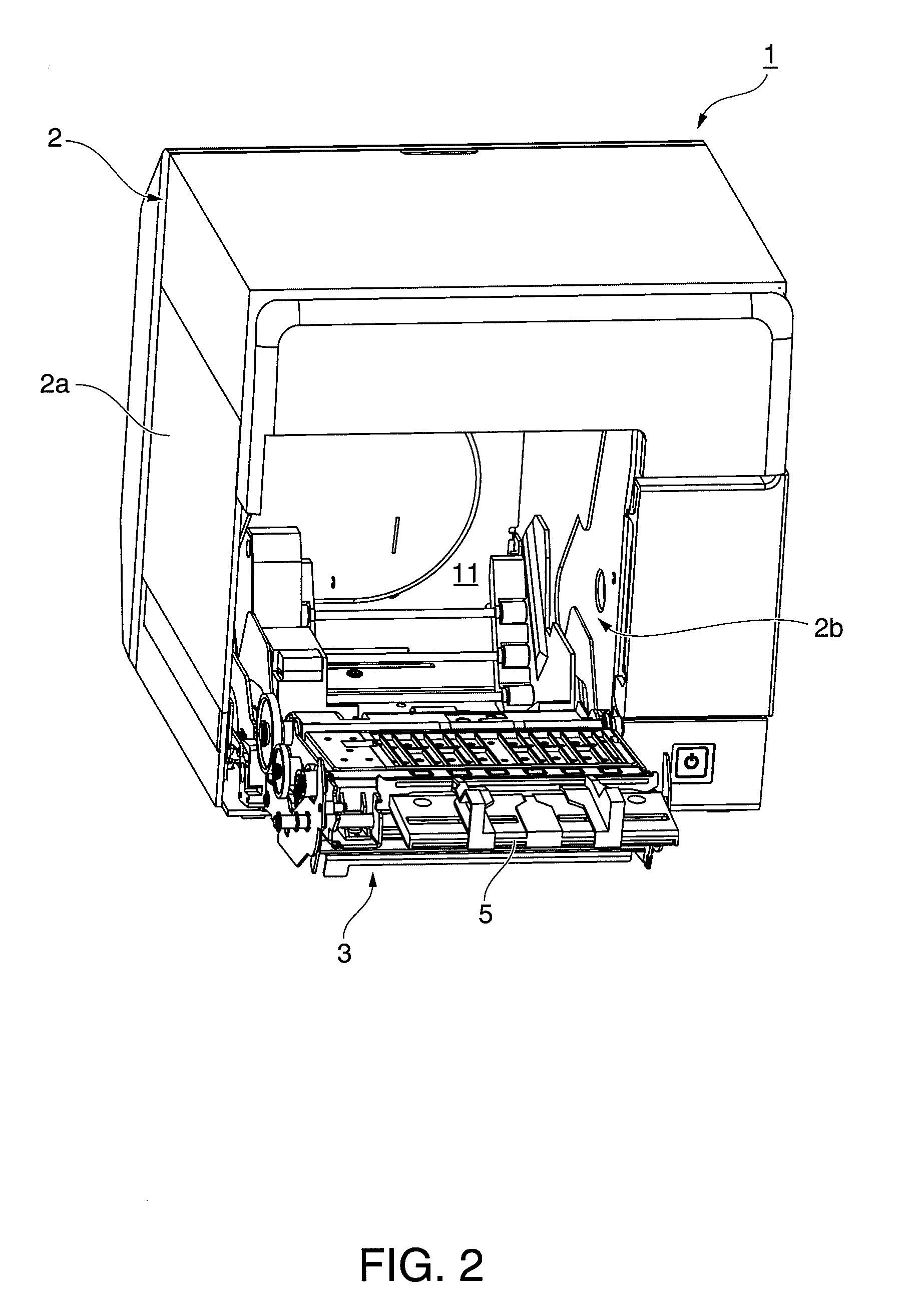
[0043]FIG. 1 is an oblique view showing an inkjet label printer according to a first embodiment of the invention. FIG. 2 is an oblique view of the label printer with the cover completely open.

[0044]The label printer 1 has a rectangular box-like body 2 and a cover 3 that opens and closes and is disposed to the front of the body 2. A paper exit 4 of a predetermined width is formed at the front of the outside case 2a part of the printer body 2. An exit guide 5 projects to the front from the bottom of the paper exit 4, and a cover opening lever 6 is disposed beside the exit guide 5. A rectangular opening 2b for loading and removing roll paper is formed in the outside case 2a below the exit guide 5 and cover opening lever 6, and this opening 2b is closed by the cover 3.

[0045]O...


PUM


Abstract

When a label printer detects the paper width, the paper width detection operation scans the transportation path in the paper width direction by the paper width detector not once but twice, and conveys the recording medium transportation distance L, which is longer than the gap length of the gap between labels and is shorter than the label length of each label, between the first and second paper width detection operations. Of the two positions detected as the left edge of the recording medium in the first and second detection operations, the position that is farthest left is used. Likewise, of the two positions detected as the right edge of the recording medium in the first and second detection operations, the position that is farthest right is used.

Description

[0001]Priority is claimed under 35 U.S.C. §119 to Japanese Patent Applications No. 2008-195869 filed on Jul. 30, 2008, and No. 2008-195870 filed on Jul. 30, 2008, the disclosures of which, including the specification, drawings and claims, are incorporated herein by reference in their entireties.BACKGROUND[0002]1. Technical Field[0003]The present invention relates to a paper width detection method used in a label printer to accurately detect the paper width of a recording medium, a printing control method for a label printer for printing to a recording medium based on the paper width detected by said paper width detection method, and to a label printer.[0004]2. Related Art[0005]Printers that print to a recording medium such as label paper having labels affixed at a constant interval along a long web liner are known from the literature. Such printers detect the width of either the recording medium liner or the labels affixed thereto by a detection operation using a paper width detecto...

Claims


Application Information

Patent Timeline
Patent Type & Authority Applications(United States)
IPC IPC(8): B41J2/01
CPCB41J3/4075B41J11/42B41J11/0095B41J11/003
Inventor SAIKAWA, TAKASHINISHIMURA, HIDEKI
Owner SEIKO EPSON CORP
Why Eureka
Try Eureka