Noise reduction apparatus and noise reduction method

Inactive Publication Date: 2010-02-04
KK TOSHIBA
View PDF16 Cites 5 Cited by
  • Summary
  • Abstract
  • Description
  • Claims
  • Application Information

AI Technical Summary

Problems solved by technology

This causes a ghost around a moving ob

Method used


Image

  • Noise reduction apparatus and noise reduction method
  • Noise reduction apparatus and noise reduction method
  • Noise reduction apparatus and noise reduction method

Examples


first embodiment

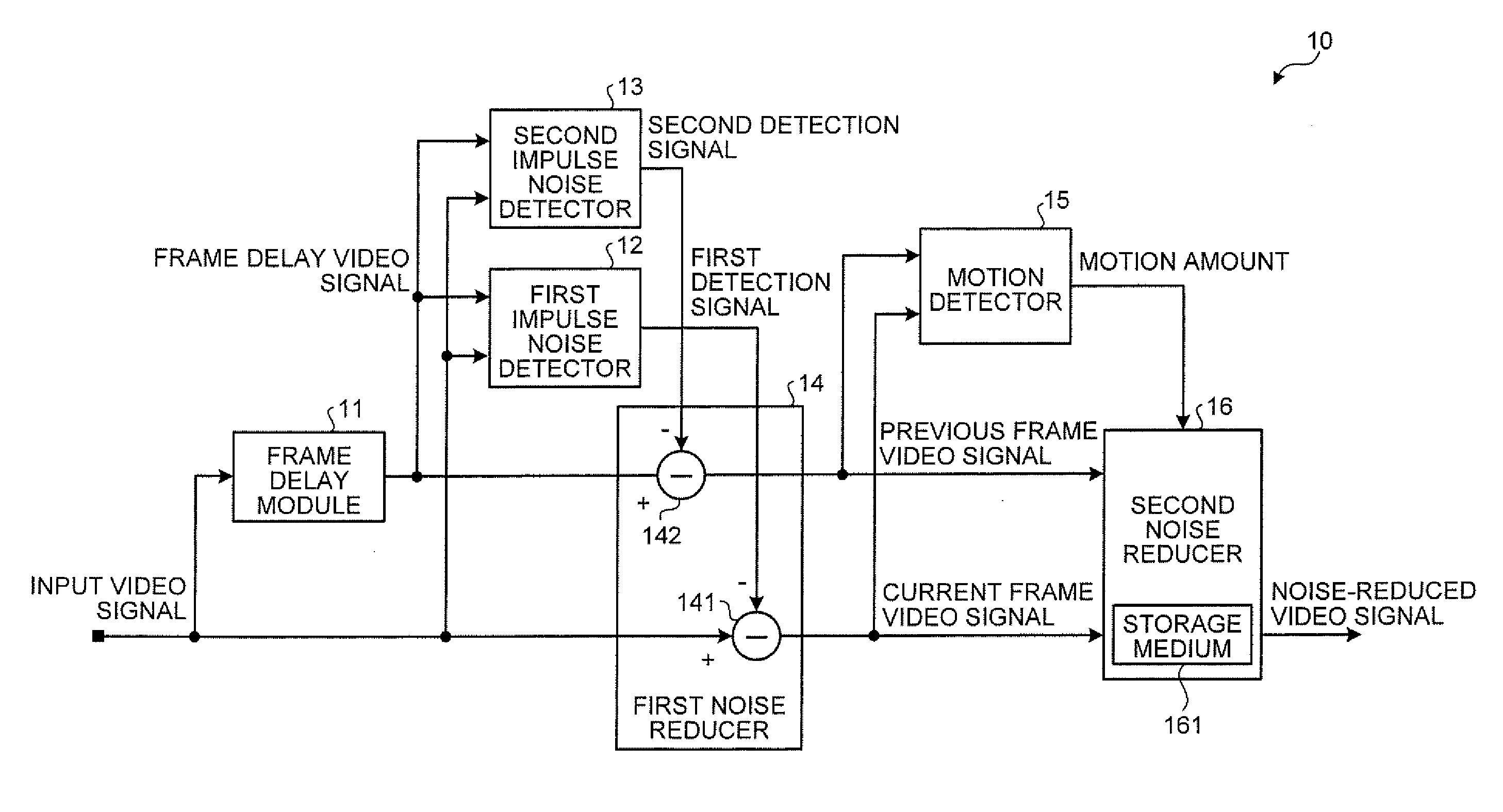
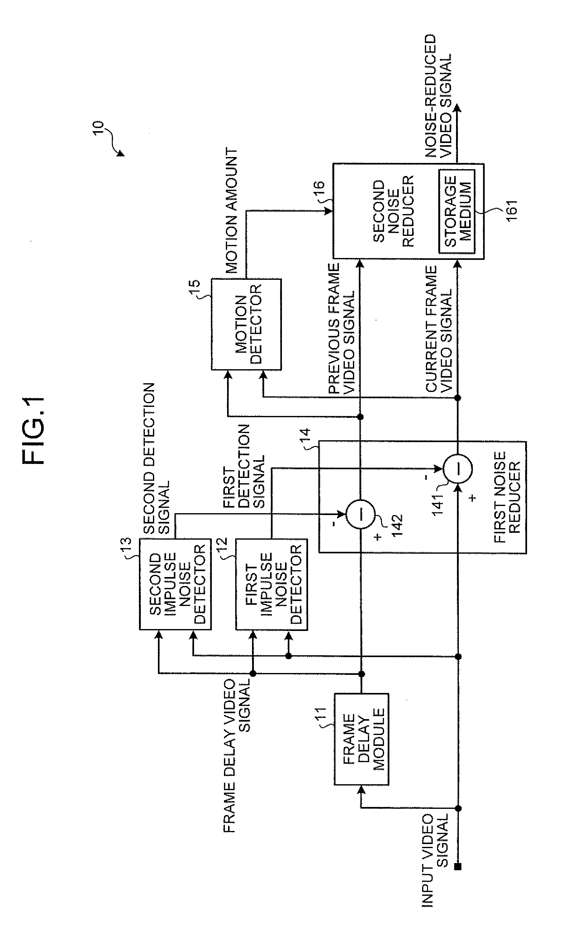
[0056]As described above, the noise reduction apparatus 10 detects the motion of video based on an input video signal (a current frame video signal) and a frame delay video signal (a previous frame video signal) from which impulse noise has been reduced. The noise reduction apparatus 10 performs noise reduction on the current frame video signal with intensity corresponding to the motion amount. Accordingly, the noise reduction apparatus 10 can reduce impulse noise components as well as other noise components from the input video signal with intensity corresponding to the video signal. Thus, it is possible to achieve a noise reduction effect suitable for the input video signal, and thereby improve the image quality of the input video signal.

[0057]While, in the example of FIG. 1, the frame delay video signal is input to the second noise reducer 16, it may not be input thereto when noise reduction is performed on the current frame video signal without using the frame delay video signa...

second embodiment

[0062]FIG. 8 is a block diagram of a noise reduction apparatus 30 according to the As illustrated in FIG. 8, the noise reduction apparatus 30 comprises a frame delay module 31, an impulse noise detector 32, a first noise reducer 33, a motion detector 34, and a second noise reducer 35. The noise reduction apparatus 30 is of loop type, in which the output of the second noise reducer 35 is input to the frame delay module 31.

[0063]The frame delay module 31 is a frame memory or the like that stores one frame of a video signal (a noise-reduced video signal described later) received from the second noise reducer 35, and outputs it to the impulse noise detector 32 as a frame delay video signal that is delayed by one frame from an input video signal input thereto from the outside. The noise components of the video signal received from the second noise reducer 35 have been reduced by the first noise reducer 33 and the second noise reducer 35.

[0064]The impulse noise detector 32 receives the f...


PUM


Abstract

According to one embodiment, a noise reduction apparatus includes a frame delay module, first and second impulse noise detectors, first and second impulse noise reducers, a motion detector, and a noise reducer. The frame delay module delays a video signal by one frame to obtain a frame delay video signal. The first and second impulse noise detectors detect impulse noise in the video signal and the frame delay video signal. The first impulse noise reducer generates a current frame video signal by reducing the impulse noise in the video signal. The second impulse noise reducer generates a previous frame video signal by reducing the impulse noise in the frame delay video signal. The motion detector detects motion amount from the current and previous frame video signals. The noise reducer reduces noise other than the impulse noise in the current frame video signal based on the motion amount.

Description

CROSS-REFERENCE TO RELATED APPLICATIONS[0001]This application is based upon and claims the benefit of priority from Japanese Patent Application No. 2008-201140, filed Aug. 4, 2008, the entire contents of which are incorporated herein by reference.BACKGROUND[0002]1. Field[0003]One embodiment of the invention relates to a noise reduction apparatus and a noise reduction method for reducing noise components of a video signal.[0004]2. Description of the Related Art[0005]Noise reduction apparatuses have been used to reduce noise in a signal. For example, Japanese Patent Application Publication (KOKAI) No. 2001-136416 discloses a noise reduction apparatus (a signal processing apparatus) that reduces noise. Specifically, the conventional noise reduction apparatus performs motion correction on an input video signal to obtain a motion-corrected video signal based on a motion vector detected from the input video signal. The noise reduction apparatus detects the noise level of the input video s...

Claims


Application Information

Patent Timeline
IPC IPC(8): H04N5/00H04N5/21H04N5/213
CPCH04N5/21H04N5/144
Inventor YAMAUCHI, HIMIO
Owner KK TOSHIBA
Why Eureka
Try Eureka