Optical reflector

a technology of optical reflectors and reflectors, which is applied in the field of lighting, can solve the problems of inefficiency and ineffectiveness of known reflectors used to reflect and direct the light output of led, and the limited potential of led lighting, especially

Inactive Publication Date: 2010-02-04
HONG KONG APPLIED SCI & TECH RES INST
View PDF6 Cites 15 Cited by
  • Summary
  • Abstract
  • Description
  • Claims
  • Application Information

AI Technical Summary

Problems solved by technology

The potential for LED lighting, especially, is currently limited, because known reflectors that are used to reflect and direct the light output from the LED are inefficient and ineffective.

Method used


Image

  • Optical reflector
  • Optical reflector
  • Optical reflector

Examples


first embodiment

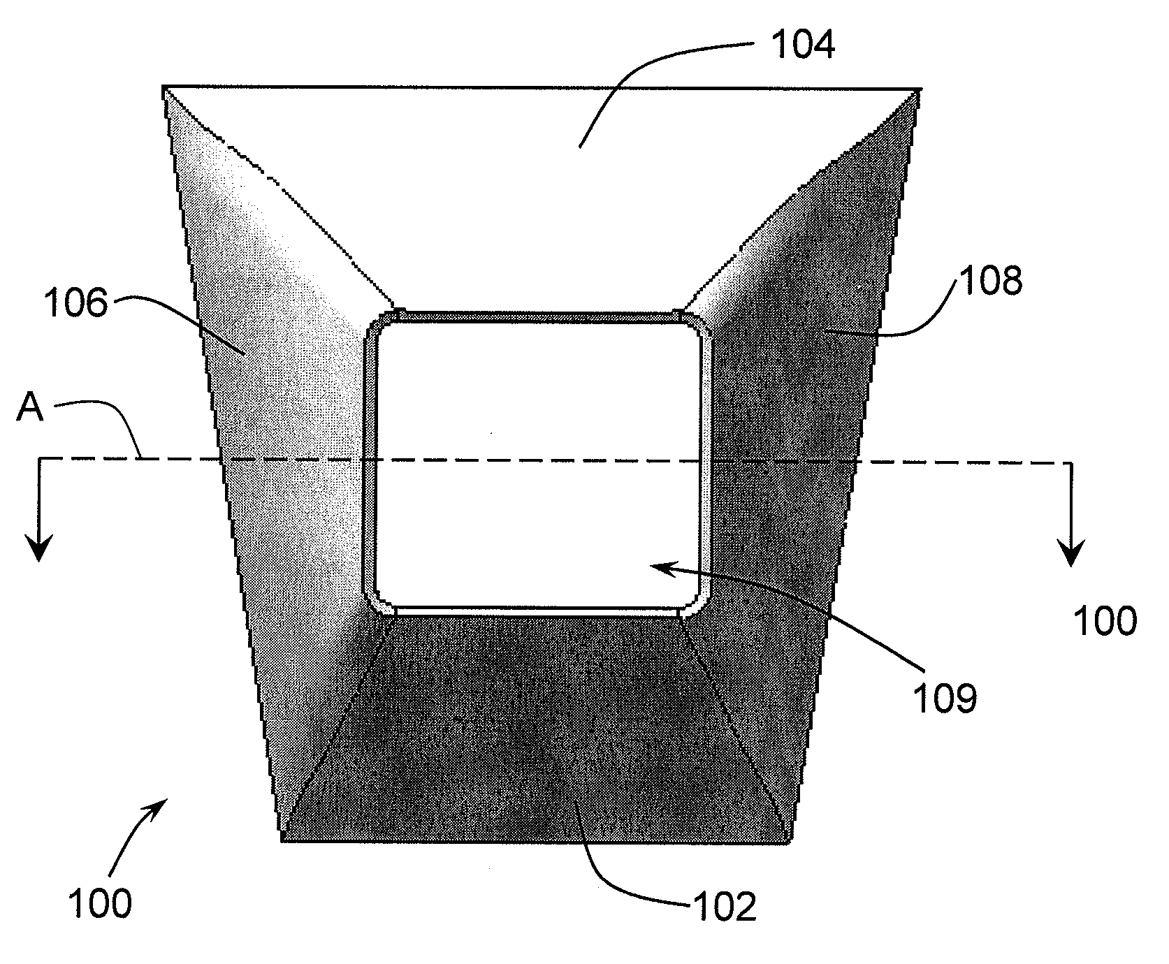
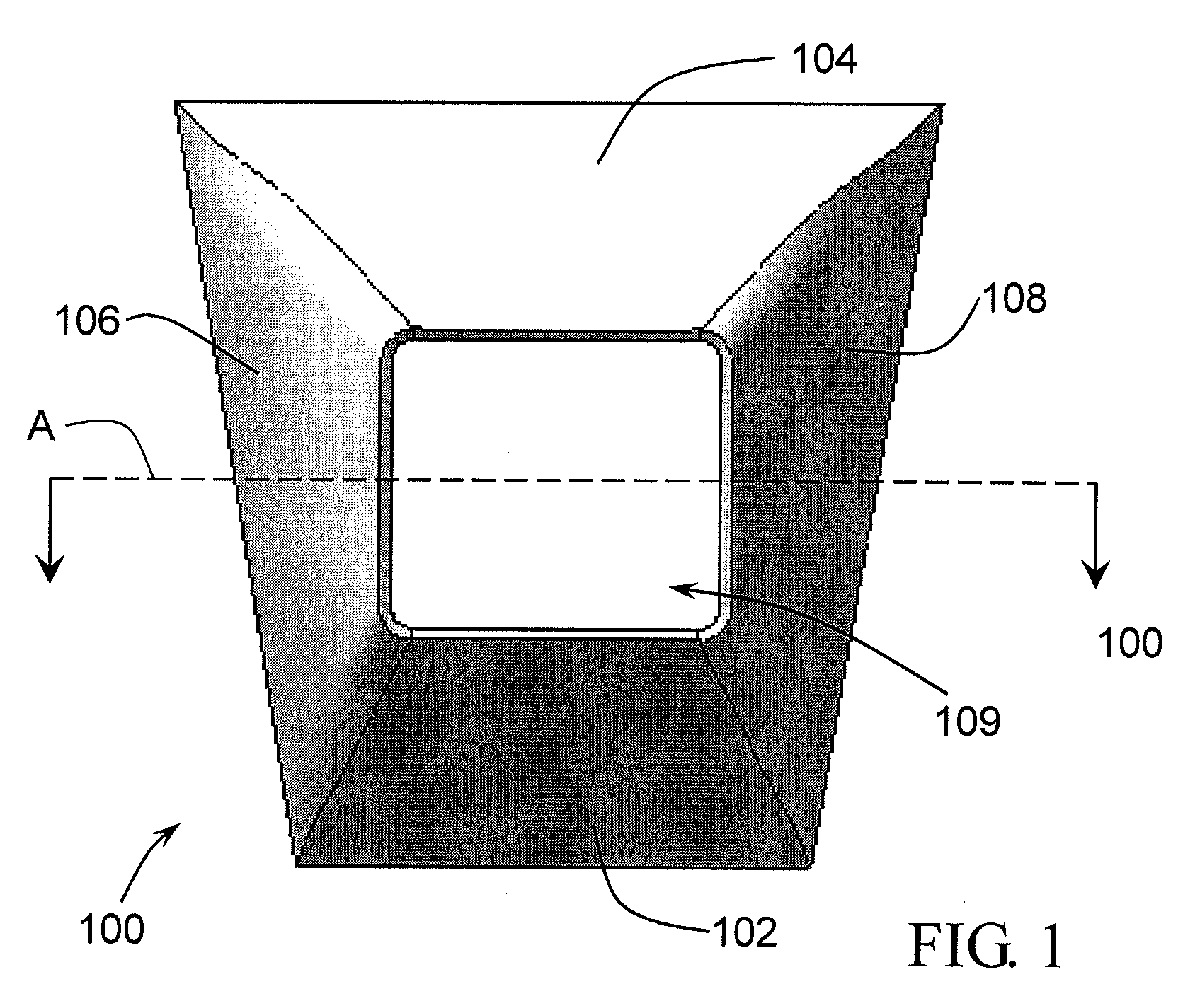
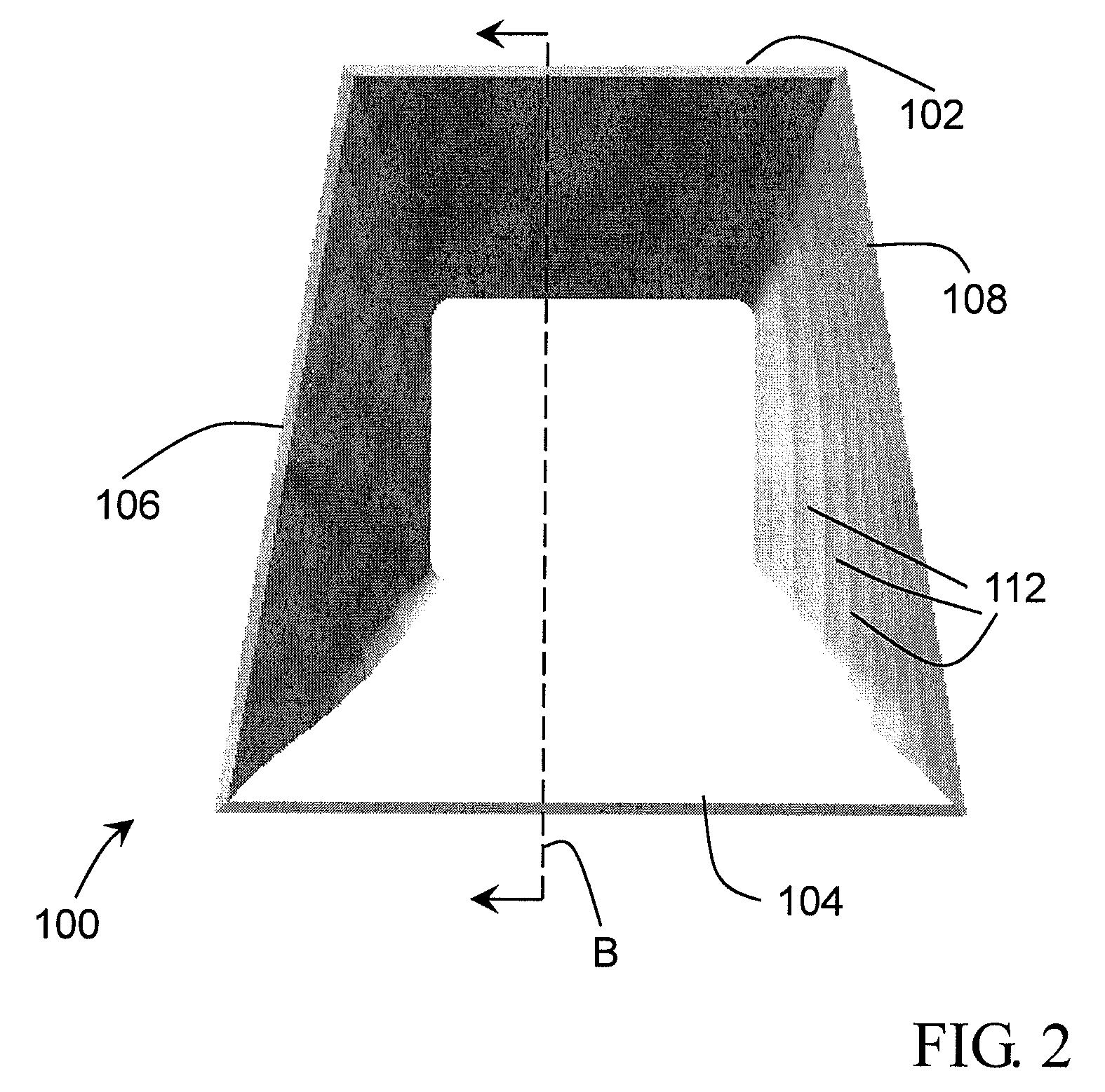
[0027]Referring now to FIGS. 1 and 2, FIG. 1 is a top view of an optical reflector 100, and FIG. 2 is a bottom view of the optical reflector 100, in accordance with the present invention. The optical reflector 100 has a front panel 102, a rear panel 104, a first side panel 106, and a second side panel 108. Together the front panel 102, the rear panel 104, the first side panel 106 and the second side panel 108 may be referred to as “the panels.” Each of the panels may angle outward from the top to the bottom of the optical reflector 100, forming a four-sided cavity inside of the optical reflector 100, the cavity flaring from top to bottom. The inner surface of each panel is generally reflective, thereby forming a reflective cavity within the optical reflector. According to one embodiment, only part of the inner surface of each panel is reflective, or at least a part of the inner surface of the cavity is reflective. The lateral alignment of the front panel 102 is generally parallel to...

second embodiment

[0047]Referring specifically to FIG. 10, the inner side of the panels has a plurality of stepped, circumferential layers 212 along the inner surface of the panels. The stepped layers 212 create a generally ribbed or gradated appearance, each of the stepped layers forming a four-edged ring-shaped ridge around the inner side of the optical reflector. The stepped layers 212 are also seen in FIG. 11. The description of the stepped layers with reference to FIGS. 2 to 4 similarly applies to the stepped layers of the second embodiment shown and described with reference to FIGS. 9 to 15.

[0048]FIG. 11 is a perspective bottom view of the optical reflector shown in FIG. 9, in accordance with a second embodiment of the present invention. The optical reflector includes the front panel 202, the rear panel 204, the first side panel 206, and the second side panel 208. The stepped inner layers 212 can also be seen in the perspective view. The optical reflector 200 has a top end 214 and a bottom end ...


PUM


Abstract

An optical reflector for emitting light generated from a light source, such as a light emitting diode. According to one embodiment, the optical reflector includes a plurality of panels forming a cavity, the cavity having a light receiving end and a light output end, the inner side of the cavity having a reflective surface, and wherein the cavity has a plurality of stepped layers along the inner surface of the cavity extending from the light receiving to the light output end; and wherein the light receiving end is configured to receive the light generated from the light source, and the stepped layers of the cavity are configured to reflect the light generated from the light source and emit the reflected light from the light output end in an asymmetrical distribution. Embodiments of present invention use a trapezoidal shape to create the asymmetrical output distribution.

Description

FIELD OF THE INVENTION[0001]The present invention relates to lighting, and more particularly, to an optical reflector for lighting.BACKGROUND OF THE INVENTION[0002]Reflectors are well known for use in directing, redirecting or focusing light generated from a light source, such as a light bulb. Reflectors are widely used, for example, in a variety of applications including indoor lighting, outdoor lighting, stage lighting, and garden lighting.[0003]Light emitting diodes (LED) are well known and have a wide range of applications, including computing and electrical devices, decorative lights, and area lights. LED are especially useful as they are efficient, producing a large amount of light using a relatively small amount of energy.[0004]The potential for LED lighting, especially, is currently limited, because known reflectors that are used to reflect and direct the light output from the LED are inefficient and ineffective. Accordingly, there is a need for a device that solves the shor...

Claims


Application Information

Patent Timeline
Patent Type & Authority Applications(United States)
IPC IPC(8): F21V7/05
CPCF21V7/09F21V7/05
Inventor LIU, YANGLIAW, BEEN YU
Owner HONG KONG APPLIED SCI & TECH RES INST
Why Eureka
Try Eureka