
Temporal laser pulse manipulation using multiple optical ring-cavities

a laser pulse and optical ring cavity technology, applied in the direction of optical radiation measurement, instruments, spectrometry/spectrophotometry/monochromators, etc., can solve the problems of high energy qs lasers that suffer from laser-induced plasma spark generation at the focused probe volume, and spatial resolution measurements with high energy qs nd:yag lasers are difficul

Inactive Publication Date: 2010-10-12
NASA
View PDF11 Cites 54 Cited by
  • Summary
  • Abstract
  • Description
  • Claims
  • Application Information

AI Technical Summary

Benefits of technology

The invention is an optical pulse stretcher that uses multiple optical cavities and beam splitters to stretch and reduce the power of an input optical beam. The placement of the optical cavities and beam splitters is optimized to account for optical beam divergence and alignment. The stretcher produces an output optical beam that is stretched and has reduced power compared to the input optical beam. The technical effects of the invention include improved optical pulse stretching and reduced power of the output optical beam.

Problems solved by technology

However, high energy QS lasers often suffer from laser-induced plasma spark generation at the focused probe volume.
The strong optical emission from the plasma spark overwhelms the weak Raman scattering signal, making spatially resolved measurements with high energy QS Nd:YAG lasers very challenging.

Method used


Image

  • Temporal laser pulse manipulation using multiple optical ring-cavities
  • Temporal laser pulse manipulation using multiple optical ring-cavities
  • Temporal laser pulse manipulation using multiple optical ring-cavities

Examples


Embodiment Construction

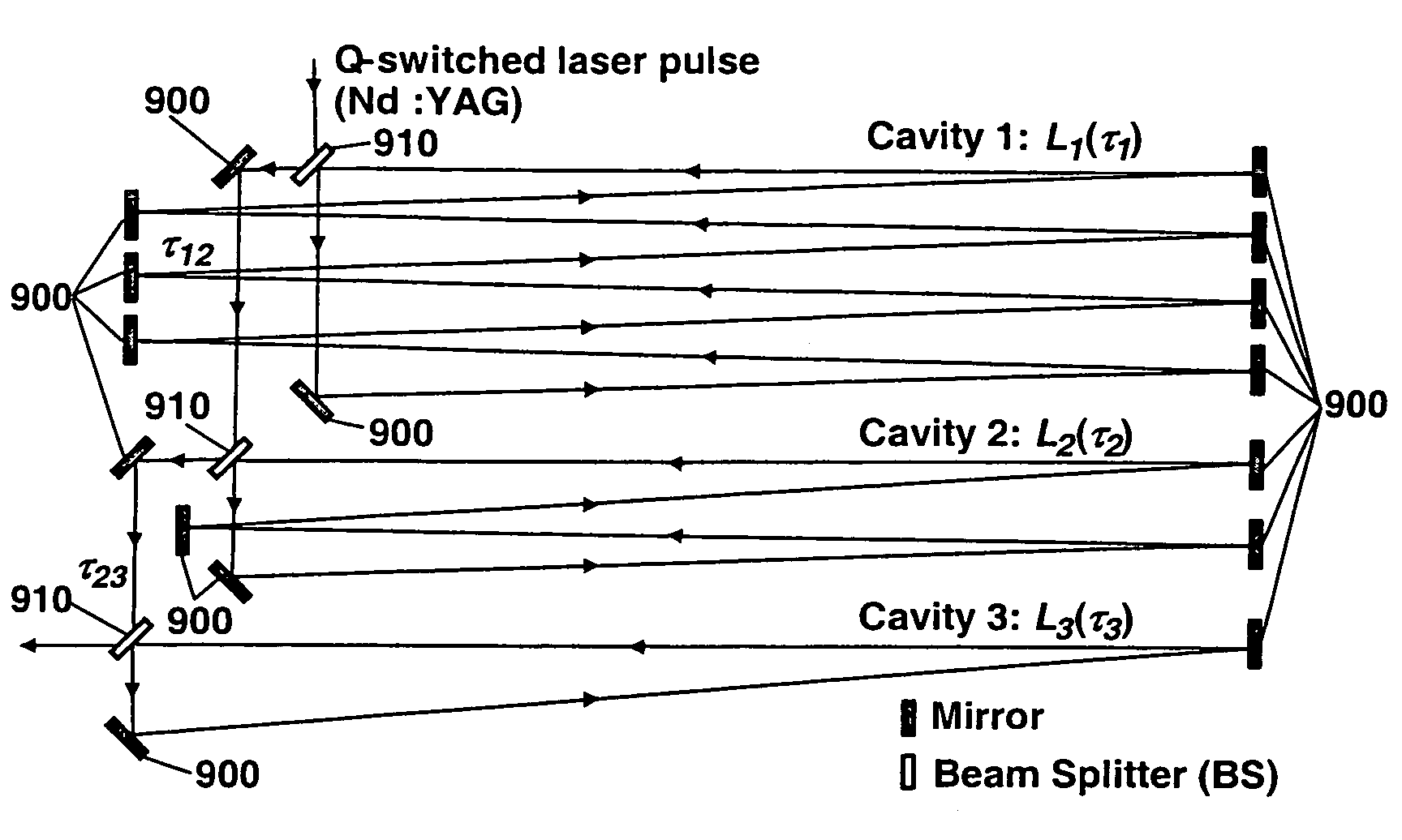
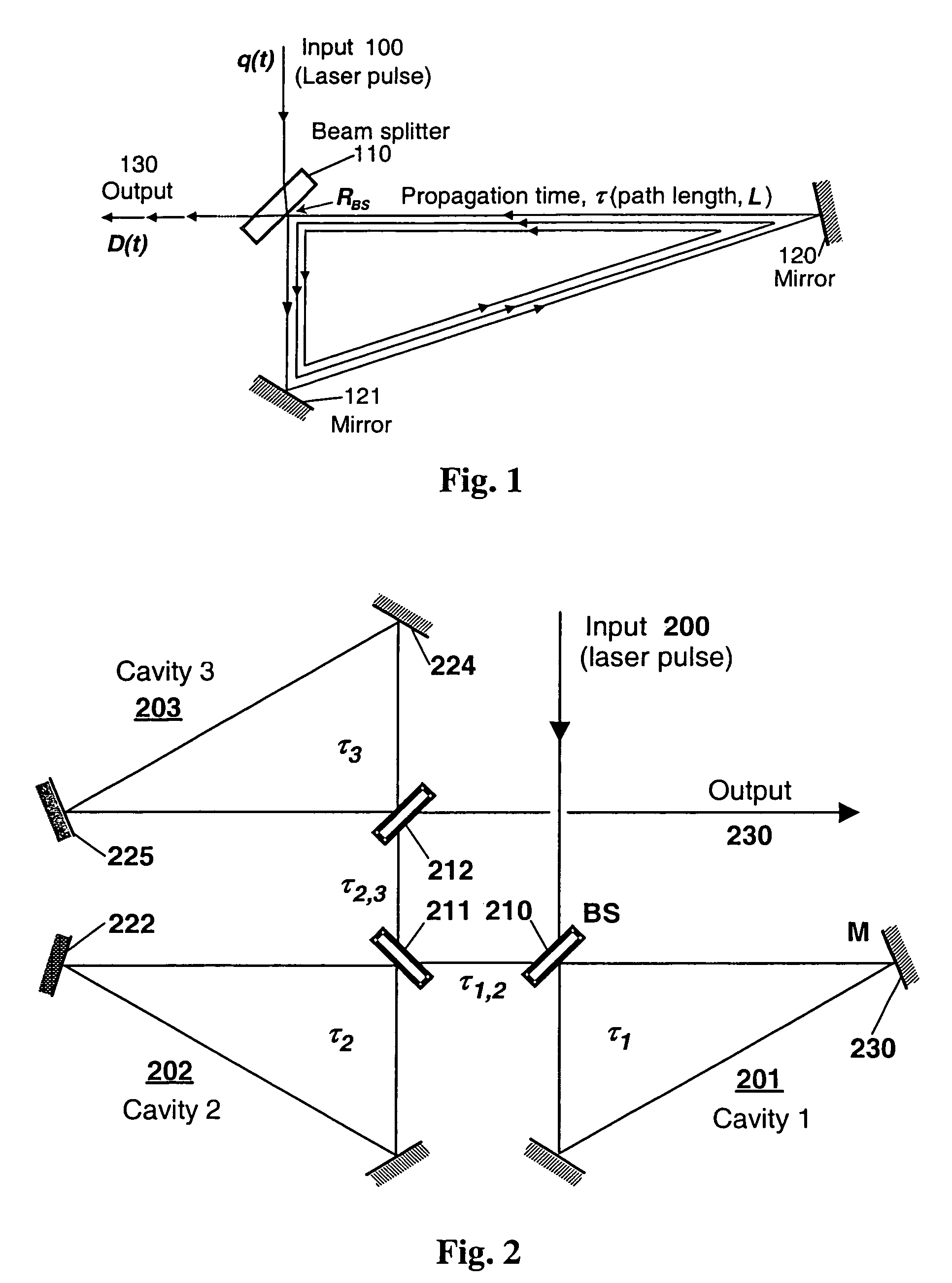
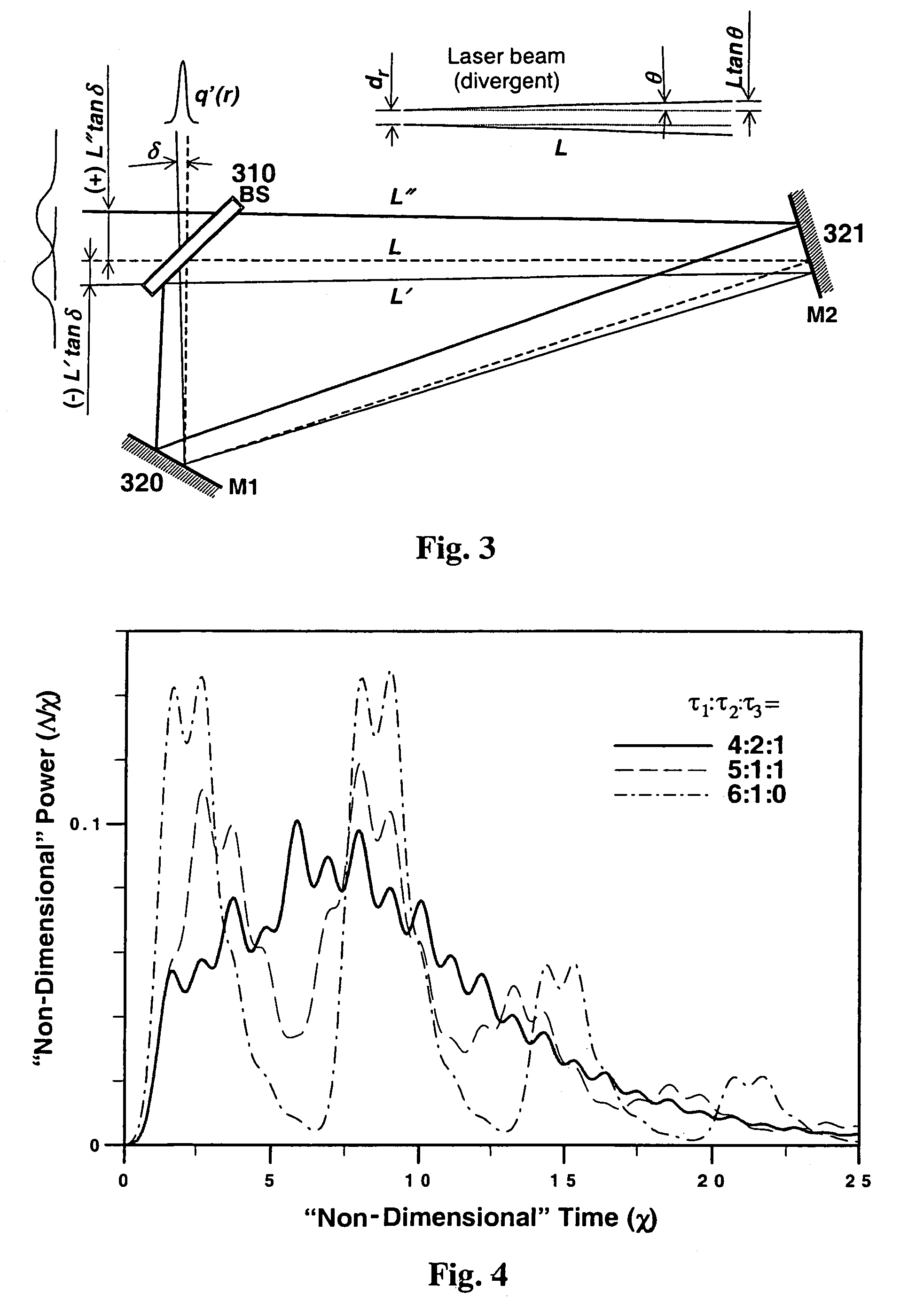
[0032]In its most general description, the present invention is directed toward a simple and passive nanosecond-long laser ‘pulse-stretcher’ using multiple optical ring-cavities. The term ‘pulse-stretcher’ is ideally suited for ns-long laser pulses and is different than the time-bandwidth-product type of pulse-stretcher that is routinely used in ultra-fast (femtosecond) laser systems. Several concepts of pulse-stretching using electro-optical devices have been reported. These other concepts were primarily intended to permit launching QS lasers pulses into optical fibers without damaging the fiber input faces. However, there are few pulse-stretching systems designed to reduce the high peak power of ns-long 532 nm laser pulses from QS Nd:YAG lasers. Many of these techniques rely on complicated and often expensive electro-optic modulators to control the intra-cavity pulse buildup in the laser.

[0033]The present invention is directed to, in several embodiments, a laser pulse-stretching s...


PUM

PropertyMeasurementUnit
reflectivityaaaaaaaaaa

Abstract

An optical pulse stretcher and a mathematical algorithm for the detailed calculation of its design and performance is disclosed. The optical pulse stretcher has a plurality of optical cavities, having multiple optical reflectors such that an optical path length in each of the optical cavities is different. The optical pulse stretcher also has a plurality of beam splitters, each of which intercepts a portion of an input optical beam and diverts the portion into one of the plurality of optical cavities. The input optical beam is stretched and a power of an output beam is reduced after passing through the optical pulse stretcher and the placement of the plurality of optical cavities and beam splitters is optimized through a model that takes into account optical beam divergence and alignment in the pluralities of the optical cavities. The optical pulse stretcher system can also function as a high-repetition-rate (MHz) laser pulse generator, making it suitable for use as a stroboscopic light source for high speed ballistic projectile imaging studies, or it can be used for high speed flow diagnostics using a laser light sheet with digital particle imaging velocimetry. The optical pulse stretcher system can also be implemented using fiber optic components to realize a rugged and compact optical system that is alignment free and easy to use.

Description

[0001]This is a Continuation-In Part of application Ser. No. 10 / 690,162 filed Oct. 15, 2003. The disclosure of the prior application(s) is hereby incorporated by reference herein in its entirety.ORIGIN OF THE INVENTION[0002]The invention described herein was made by employees of the United States Government and may be manufactured and used by or for the Government for Government purposes without payment of any royalties thereon or therefore.BACKGROUND OF THE INVENTION[0003]1. Field of Invention[0004]The present invention relates to production of specific types of laser light that can be used in analysis of certain systems. In particular, the present invention is directed to methods for splitting up a pulsed laser beam into multiple pulsed beams, each eventually traveling in the same direction to a target. The manipulated pulses may be beneficially used in ultrahigh-speed imaging and other applications.[0005]2. Description of Related Art[0006]Non-intrusive, laser-based optical diagno...

Claims


Application Information

Patent Timeline
Patent Type & Authority Patents(United States)
IPC IPC(8): H01S3/082
CPCB23K26/0622H01S3/0057
Inventor NGUYEN, QUANG-VIETKOJIMA, JUN
Owner NASA
Learn More