Image projection system and method

a projection system and projection method technology, applied in the field of projection systems and methods, can solve the problems of inability to correct the image processing unit, the spatial accuracy is compromised, and the focus changes, so as to achieve the effect of reducing the length of the optical path and the throw ratio, and optimum image quality

Active Publication Date: 2008-06-10
APPLE INC +1
View PDF71 Cites 51 Cited by
  • Summary
  • Abstract
  • Description
  • Claims
  • Application Information

AI Technical Summary

Benefits of technology

[0013]The present invention is a compact rear projection system using a rear projection transmissive screen with an integral Fresnel collimation lens. Another embodiment of the invention can be a compact front projection system that is placed very close to a reflective screen.

Problems solved by technology

The projection light engine and the optical reflection assembly are designed to minimize optical anomalies and can compromise on

Method used


Image

  • Image projection system and method
  • Image projection system and method
  • Image projection system and method

Examples


Embodiment Construction

[0072]Referring now to FIG. 3A, a first attempt at reducing cabinet thickness T (see FIG. 2A), could involve reducing the angle α. Accordingly, a projection system 6″ (i.e. an off-axis projection system) is shown having the same components as on-axis projection system 6′, however, the planar mirror 8 is placed at a shallower angle with respect to display surface 20. This has the desired effect of reducing cabinet thickness from a thickness of T to a thickness of T′. However, the resulting image now has keystone distortion (see FIG. 3B) in which the image I′ produced by the off-axis projection system 6″ is now distorted with respect to the original image I (see FIG. 2B). The keystone distortion involves shrinking the image I′ in the horizontal direction near the bottom of the image I′ while stretching the image I′ in the horizontal direction near the top of the image I′. Also, image I′ is stretched in the vertical direction.

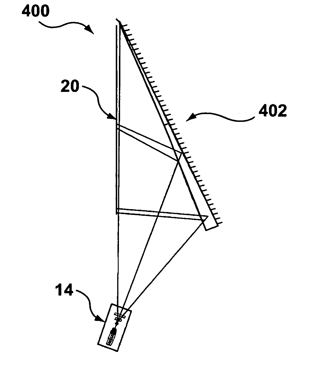
[0073]Referring now to FIG. 4A shown therein is a rear proje...


PUM


Abstract

An image projection system and method is presented for optically projecting an image onto a display surface with visually correct geometry and optimum image quality. The projection system includes an image processing unit for receiving the input image data and generating distortion-compensated image data to compensate for ensuing spatial distortions in the projection system, a projection light engine for receiving the distortion-compensated image data and projecting a distortion-compensated optical image that corresponds to the distortion-compensated image data; and, an optical reflection assembly comprising at least one curved mirror positioned in the optical path of the distortion-compensated optical image emerging from the projection light engine for producing a displayed optical image with reduced distortion on the display surface. The image processing unit distortion-compensates the input image data such that the optical and spatial distortions associated with the projection light engine and optical reflection assembly are substantially reduced in the displayed optical image.

Description

CROSS-REFERENCE TO RELATED APPLICATION[0001]This application claims priority from U.S. Provisional Patent Application Ser. No. 60 / 438,675 filed Jan. 8, 2003.FIELD OF THE INVENTION[0002]This invention relates to projection systems and methods and more particularly to a short throw projection system and method which combines optics and image processing for reducing optical path length while maintaining optimum image quality.BACKGROUND OF THE INVENTION[0003]In a front projection system, the projector and viewer are on the same side of the display surface, with the image from the projector reflecting from the display surface to the viewer. FIG. 1A shows a standard prior art eight-element projection lens 5, which can take an input optical image 2 and project an expanded output optical image 3. FIG. 1B shows a projection light engine 6 that uses the eight element projection lens 5 to project an image directly on a display surface 20. This is an example of an on-axis projection system in w...

Claims


Application Information

Patent Timeline
IPC IPC(8): G03B21/14G03B21/28G02B5/10G02B13/18G02B17/00G02B17/06G02B26/08G03B21/00G03B21/10G03B21/56G03B21/60H04NH04N1/00H04N3/23H04N5/57H04N5/74H04N17/00
CPCG02B17/06G02B17/0621G03B21/10G03B21/28H04N5/7408H04N9/3185H04N9/3197H04N5/57H04N2005/7466H04N2005/745G02B13/18G03B21/00H04N5/74
Inventor RAMACHANDRAN, GOPALPRIOR, GREGORY A.
Owner APPLE INC
Why Eureka
Try Eureka