Electrowetting display

a technology of electronic display and display screen, applied in the field of electronic display apparatus, can solve the problems of physical large size, limited resolution, and again limited resolution

Inactive Publication Date: 2005-12-29
MICRON TECH INC
View PDF6 Cites 51 Cited by
  • Summary
  • Abstract
  • Description
  • Claims
  • Application Information

AI Technical Summary

Benefits of technology

[0012] The present invention comprises construction of a display from display elements that are actuated using the physical principle of electrowetting. In one embodiment, pores within porous silicon are filled with an ionic and an optically reflective electronic conductor, and actuated by application of an electric potential across the pore. An image is then formed on an array of such pores by applying an appropriate voltage to each pore of the array to create an optical image in the light reflected off the electronic conductors. Such a display may be constructed to have very high resolution, making it desirable for creating real-time holographic images, or for creating high-resolution mask images for use in photolithography.

Problems solved by technology

This CRT apparatus is well-understood and relatively inexpensive, but is physically large in size, and its resolution is limited by the slot mask and screen phosphor geometry.
Such a display can be quite flat, but resolution is again limited by the physical size of the polarizing and color filters, and the liquid crystal cell.
Other display mechanisms exist, but most have some physical attribute that limits the resolution displayable by the apparatus.

Method used


Image

  • Electrowetting display
  • Electrowetting display
  • Electrowetting display

Examples


Embodiment Construction

[0013] In the following detailed description of sample embodiments of the invention, reference is made to the accompanying drawings which form a part hereof, and in which is shown by way of illustration specific sample embodiments in which the invention may be practiced. These embodiments are described in sufficient detail to enable those skilled in the art to practice the invention, and it is to be understood that other embodiments may be utilized and that logical, mechanical, electrical, and other changes may be made without departing from the spirit or scope of the present invention. The following detailed description is, therefore, not to be taken in a limiting sense, and the scope of the invention is defined only by the appended claims.

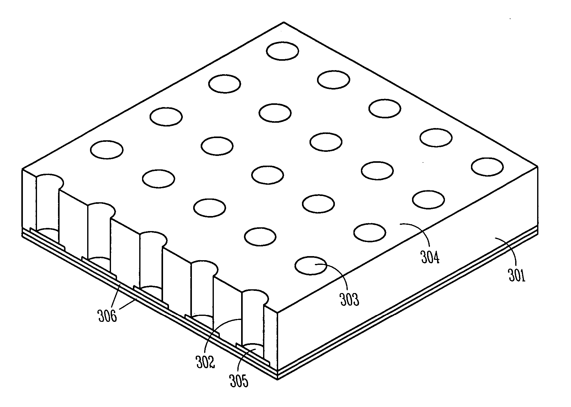
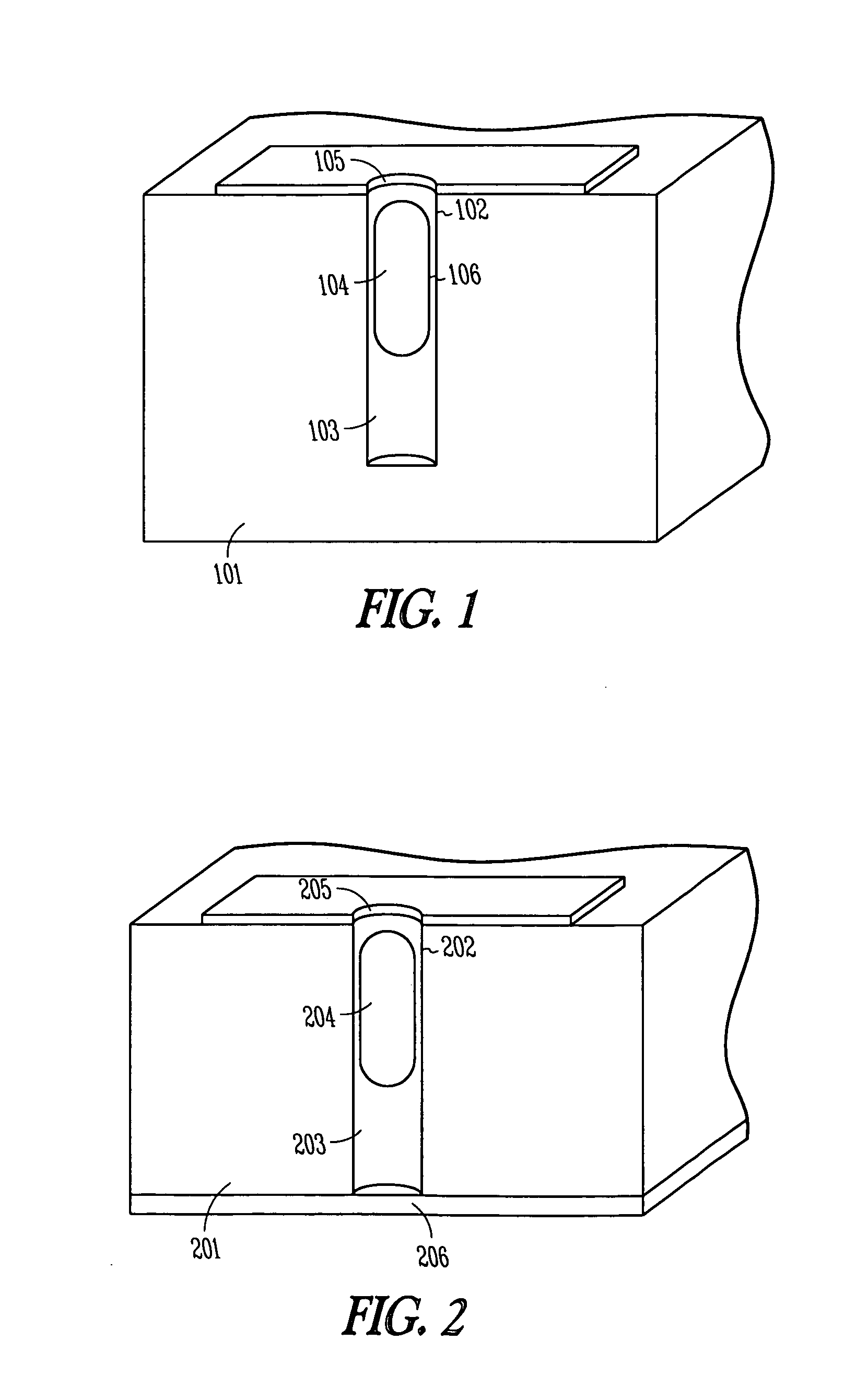
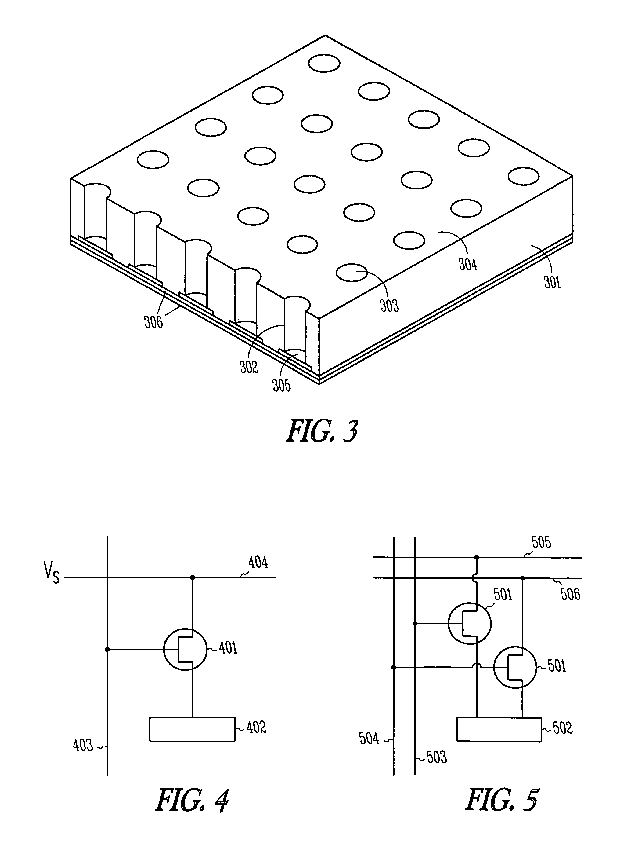
[0014] The present invention comprises use of electrowetting principles in porous silicon to create a display apparatus. The display apparatus is controlled by an electronic control matrix, which creates an electric potential across selected sil...


PUM


Abstract

The present invention comprises construction of a display from display elements that are actuated using the physical principle of electrowetting. In one embodiment, pores within porous silicon are filled with an ionic and an optically reflective electronic conductor, and actuated by application of an electric potential across the pore. An image is then formed on an array of such pores by applying an appropriate voltage to each pore of the array to create an optical image in the light reflected off the electronic conductors. Such a display may be constructed to have very high resolution, making it desirable for creating real-time holographic images, or for creating high-resolution mask images for use in photolithography.

Description

[0001] This application is a Divisional of U.S. application Ser. No. 09 / 258,743, filed Feb. 26, 1999, which is incorporated herein by reference,FIELD OF THE INVENTION [0002] The invention relates generally to an electronic display apparatus, and specifically to use of electrowetting to actuate pixels in a display. BACKGROUND OF THE INVENTION [0003] A number of display types exist for the purpose of physically displaying a representation of an image formed electronically, such as on a computer. Standard Cathode-Ray Tube (CRT) displays are the most common, but are supplemented by technologies such as Liquid Crystal Display (LCD) and gas plasma display when space is a concern. Each of these display types has characteristics that are advantageous for certain applications, but all share certain characteristics that limit the use of electronic displays to certain applications. [0004] A standard CRT display used with most personal computer systems receives three signals of varying intensit...

Claims


Application Information

Patent Timeline
Patent Type & Authority Applications(United States)
IPC IPC(8): G02B26/02G09G3/28G09G3/34
CPCG02B26/005G09G2310/0262G09G3/3433
Inventor GLASS, THOMAS R.
Owner MICRON TECH INC
Why Eureka
Try Eureka