Ear mold for a hearing device

a hearing device and mold technology, applied in the field of ear molds for hearing devices, can solve the problems of snap-on connection not being reliably maintained, earpieces usually reversibly deformed, soft material abrasion, etc., and achieves reliable, durably-robust, and easy removal of the connection. , the effect of avoiding abrasion

a hearing device and mold technology, applied in the field of ear molds for hearing devices, can solve the problems of snap-on connection not being reliably maintained, earpieces usually reversibly deformed, soft material abrasion, etc., and achieves reliable, durably-robust, and easy removal of the connection. , the effect of avoiding abrasion

US20100027825A1Inactive Publication Date: 2010-02-04SIEMENS MEDICAL EQUIPMENT

Image

  • Ear mold for a hearing device
  • Ear mold for a hearing device
  • Ear mold for a hearing device

Examples


Embodiment Construction

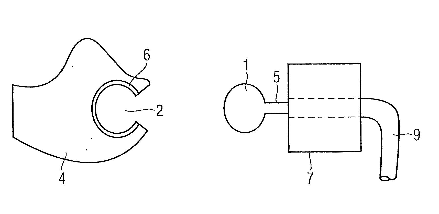
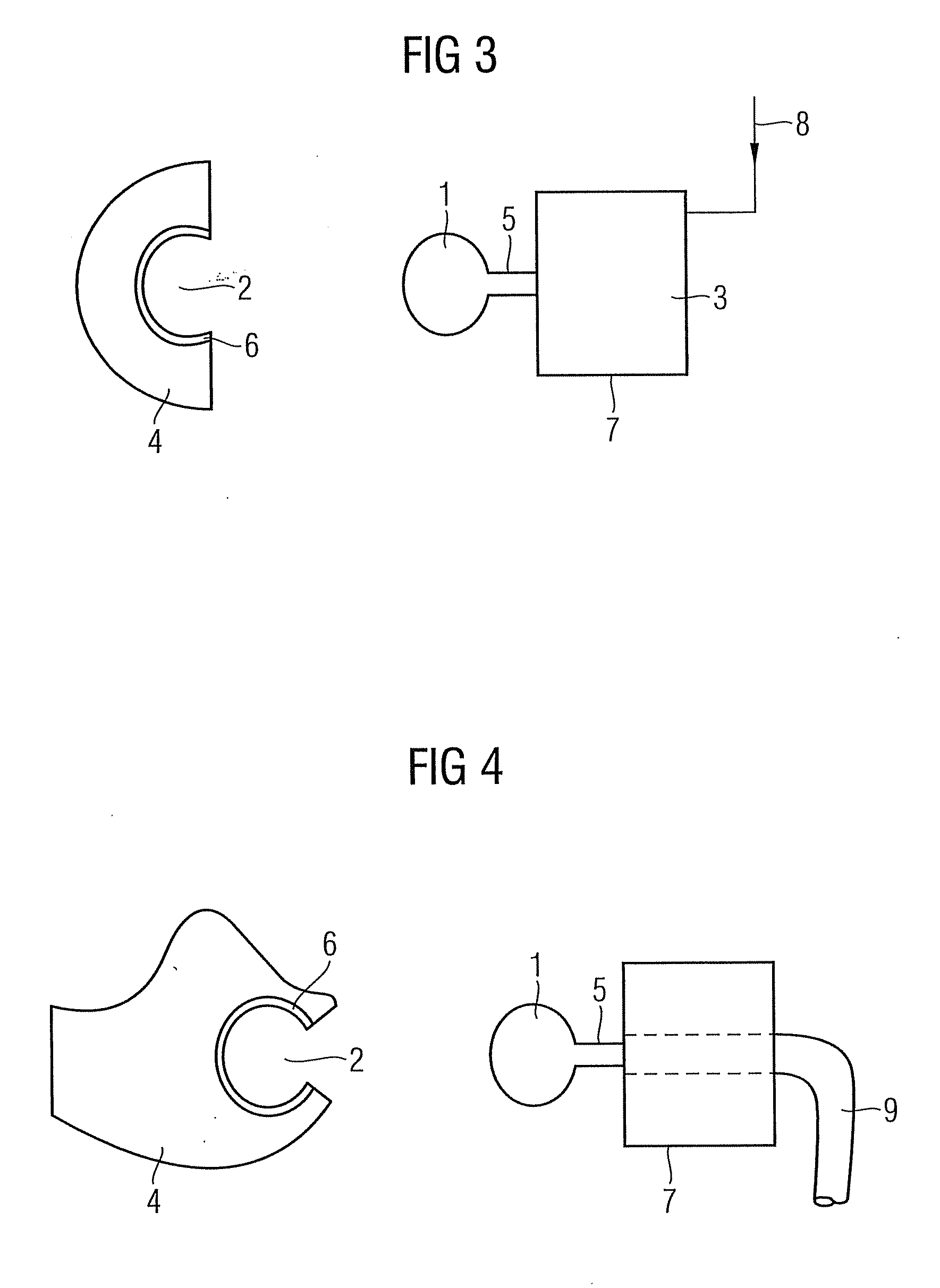
[0027]FIG. 3 shows a cross-section through an inventive ear mold 4 as well as a schematic representation of an inventive receiver 3 with a snap-on element 1. The ear mold 4 is made of a soft plastic, for instance silicon, and has a spherical opening 2, which is lined with a hard layer 6. The hard layer 6 makes the soft surface of the opening into a hard one, into which the snap-on element 1 of the receiver 3 can engage. This produces a robust, abrasion-free connection. The snap-on element 1 is likewise spherical and is fixedly connected to a housing 7 of the receiver 3 by means of a connecting element 5. The snap-on element 1 and connecting element 5 are preferably produced in one piece and from metal. The connecting element 5 is molded in a cylindrical fashion for instance. The receiver housing 7 is likewise made of metal. The snap-on element 1 is welded to the receiver housing for a secure hold. A hearing device wearer can thus easily connect the receiver 3 to a selected ear mold ...


PUM


Abstract

In one aspect an ear mold for a hearing device is provided. The ear mol includes an opening for accommodating a snap-on element arranged on a receiver or a sound tube, with the opening being lined with a hard layer. A device having a receiver or a sound tube and a snap-on element are likewise specified.

Description

CROSS REFERENCE TO RELATED APPLICATIONS[0001]This application claims priority of German application No. 10 2008 036 0258.1 DE filed Aug. 4, 2008, which is incorporated by reference herein in its entirety.FIELD OF INVENTION[0002]The invention relates to an ear mold for a hearing device, a receiver or a sound tube with a snap-on element and a behind-the-ear hearing device.BACKGROUND OF INVENTION[0003]In the case of the behind-the-ear and in-the-ear hearing devices found on the market, it is generally necessary to connect an earpiece which is adjusted to the auditory canal of the hearing device wearer to an in-the-ear loudspeaker. Different solutions exist depending on the embodiment of the earpiece in order to produce a secure connection.[0004]For individually adjusted earpieces, also known as ear molds, the ear shape of a hearing device user is inspected and a shell or body is manufactured in a fixed and / or hard embodiment in accordance herewith. The hard embodiment is for instance a...

Claims


Application Information

Patent Timeline
04 Feb 2010
Publication
US20100027825A1
IPC
H04R25/00
CPC
H04R25/60; H04R25/652; H04R25/658; H04R2225/63; H04R25/604; H04R2225/025; H04R2225/0213; H04R2225/57
Inventors
FICKWEILER, WERNER; GOMMEL, ULI