Nested bearing cages

a technology of bearing cages and cages, which is applied in the direction of bearing unit rigid support, machines/engines, liquid fuel engines, etc., can solve the problems of spring cages, limited axial and radial space available for bearings, and significant engine dynamics

Active Publication Date: 2010-02-04
GENERAL ELECTRIC CO
View PDF20 Cites 44 Cited by
  • Summary
  • Abstract
  • Description
  • Claims
  • Application Information

AI Technical Summary

Benefits of technology

[0006]According to another aspect of the invention, a bearing assembly for a gas turbine engine includes: (a) a first bearing cage having: (i) an annular first bearing race; (ii) an annular first mounting ring secured to a stationary member of the engine; and (iii) an annular array of axially-extending first spring arms interconnecting the first bearing race and the first mounting ring; (b) a rolling-element first bearing mounted in the first bearing support ring; (c) a second bearing cage comprising: (i) an annular second bea...

Problems solved by technology

Particularly in large aircraft turbofan engines, it has been demonstrated that engine dynamics will suffer significantly if such cages are not used.
These sumps have limited axial and radial space available to be used for bearings, spring cages, intermediate gearbox mounting, damper housings, air and oil seals, ...

Method used


Image

  • Nested bearing cages
  • Nested bearing cages
  • Nested bearing cages

Examples


Embodiment Construction

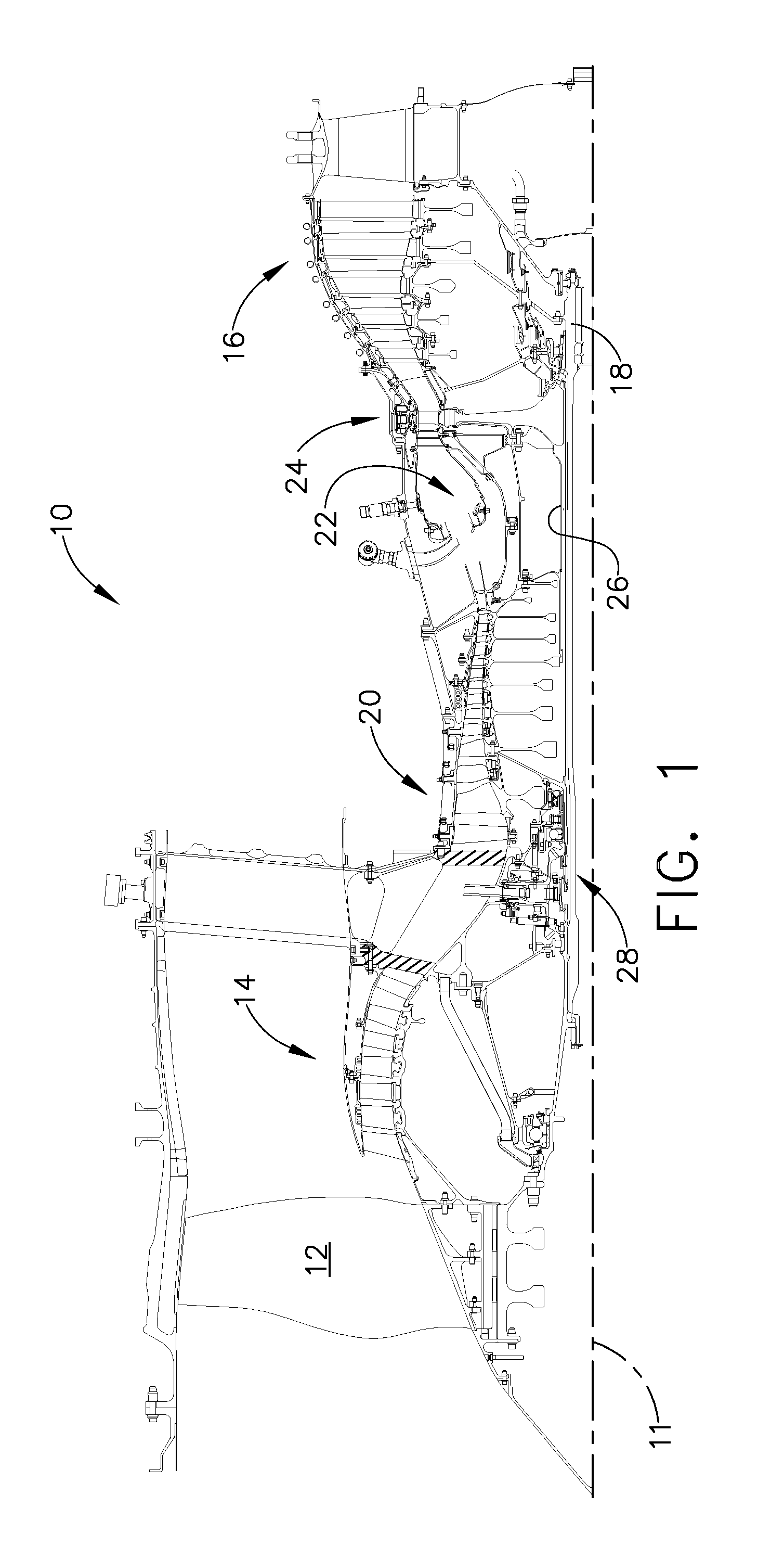
[0012]Referring to the drawings wherein identical reference numerals denote the same elements throughout the various views, FIG. 1 depicts a gas turbine engine 10. The engine 10 has a longitudinal axis 11 and includes a fan 12, a low pressure compressor or “booster”14 and allow pressure turbine (“LPT”) 16 collectively referred to as a “low pressure system”. The LPT 16 drives the fan 12 and booster 14 through an inner shaft 18, also referred to as an “LP shaft”. The engine 10 also includes a high pressure compressor (“HPC”) 20, a combustor 22, and a high pressure turbine (“HPT”) 24, collectively referred to as a “gas generator” or “core”. The HPT 24 drives the HPC 20 through an outer shaft 26, also referred to as an “HP shaft”. Together, the high and low pressure systems are operable in a known manner to generate a primary or core flow as well as a fan flow or bypass flow. While the illustrated engine 10 is a high-bypass turbofan engine, the principles described herein are equally ap...


PUM


Abstract

A gas turbine engine bearing cage assembly includes: a first bearing cage having: an annular first bearing support ring; an annular first mounting flange; and an annular array of axially-extending first spring arms interconnecting the first bearing support ring and the first mounting flange, the first spring arms defining an outer diameter; and a second bearing cage having: an annular second bearing support ring; an annular second mounting ring, the second mounting ring defining an inner diameter greater that the outer diameter; and an annular array of axially-extending second spring arms interconnecting the second bearing support ring and the second mounting ring, the second spring arms defining spaces therebetween. The bearing cages are sized such that the first bearing cage can be received within the second bearing cage. The spaces are positioned to receive the first spring arms, permitting independent flexing motion of the first and second spring arms.

Description

BACKGROUND OF THE INVENTION[0001]This invention relates generally to gas turbine engine bearings and more particularly to mounting arrangements for such bearings.[0002]It is known to support bearings, such as the large rolling-element bearings used in gas turbine engines, using spring centering cages. The spring constant of such cages can be manipulated to provide a desired stiffness and consequently affect the dynamics and vibration modes of the engine. Particularly in large aircraft turbofan engines, it has been demonstrated that engine dynamics will suffer significantly if such cages are not used.[0003]Many gas turbine engines have at least one sump that includes two or more rolling element bearings positioned in close proximity to each other. These sumps have limited axial and radial space available to be used for bearings, spring cages, intermediate gearbox mounting, damper housings, air and oil seals, air pressurization channels, and oil transport between parts of the sump. Th...

Claims


Application Information

Patent Timeline
IPC IPC(8): F16C33/38
CPCF01D25/164F02C7/06F16C19/545F05D2240/52F16C27/04F16C19/54F16C27/045F16C2360/23
Inventor KINNAIRD, RAY HARRISFANG, NING
Owner GENERAL ELECTRIC CO
Why Eureka
Try Eureka