

Subcutaneously implantable lead including distal fixation mechanism
- Summary
- Abstract
- Description
- Claims
- Application Information
AI Technical Summary
Problems solved by technology
Method used
Image

Examples
Embodiment Construction
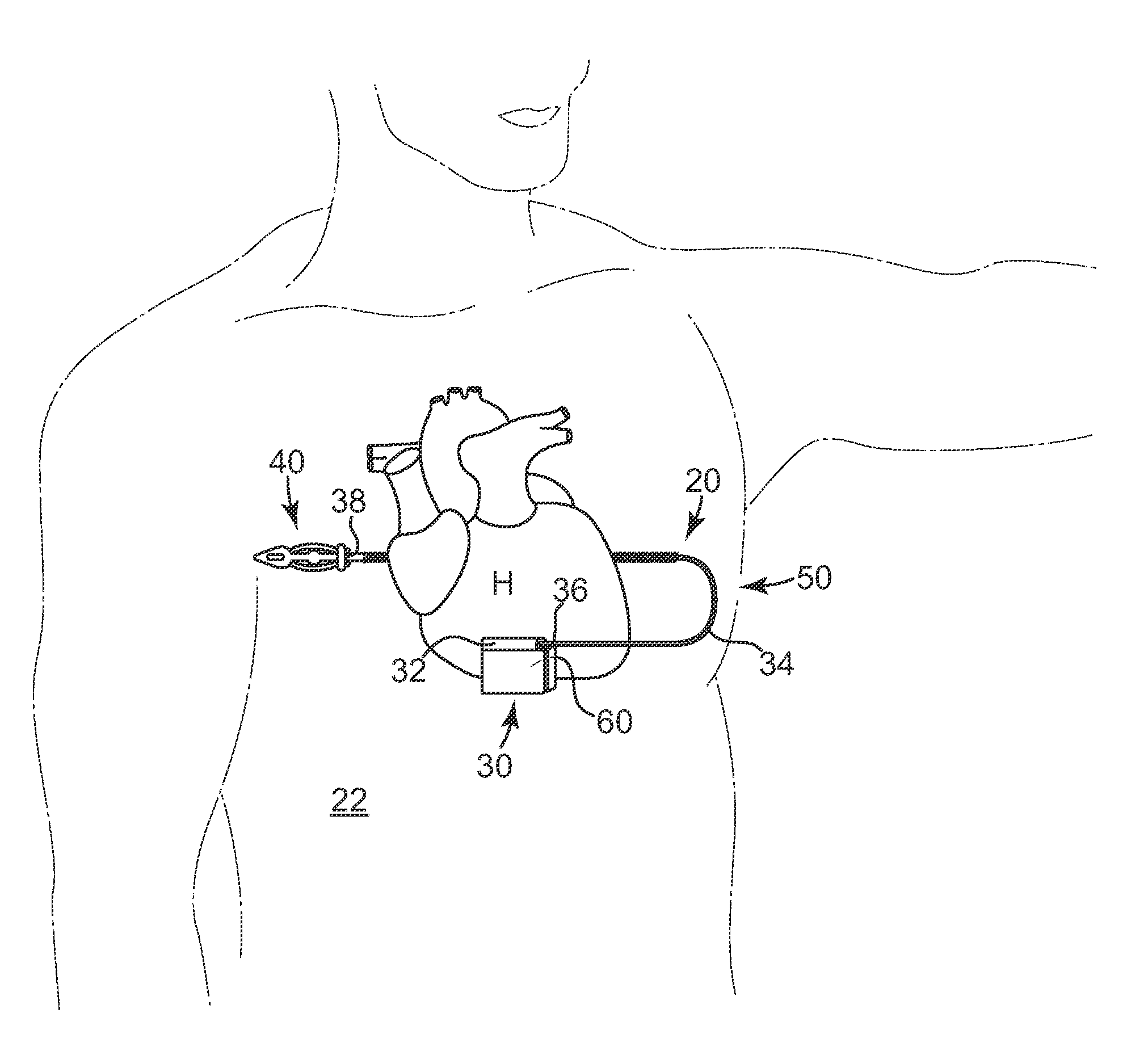
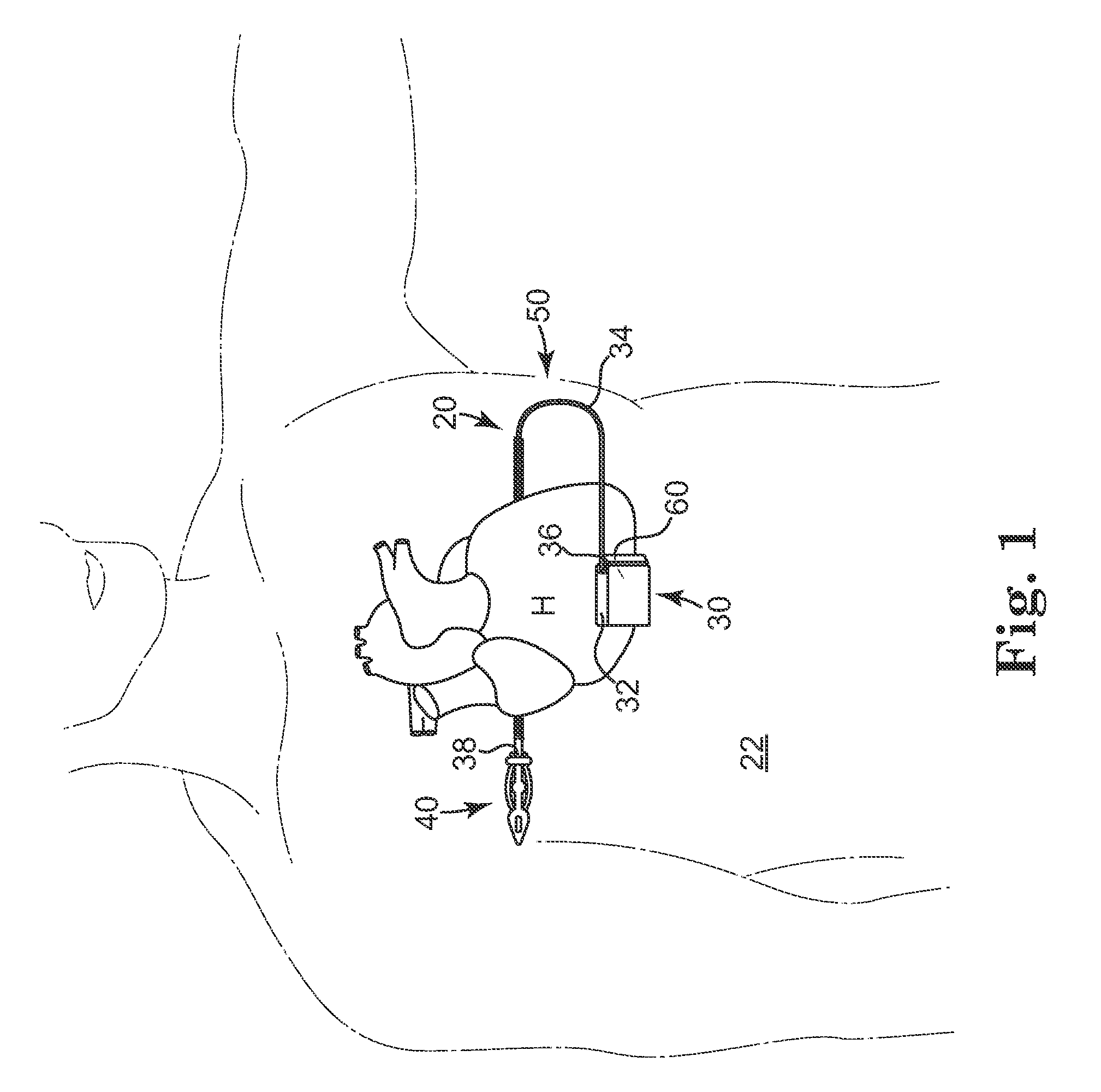
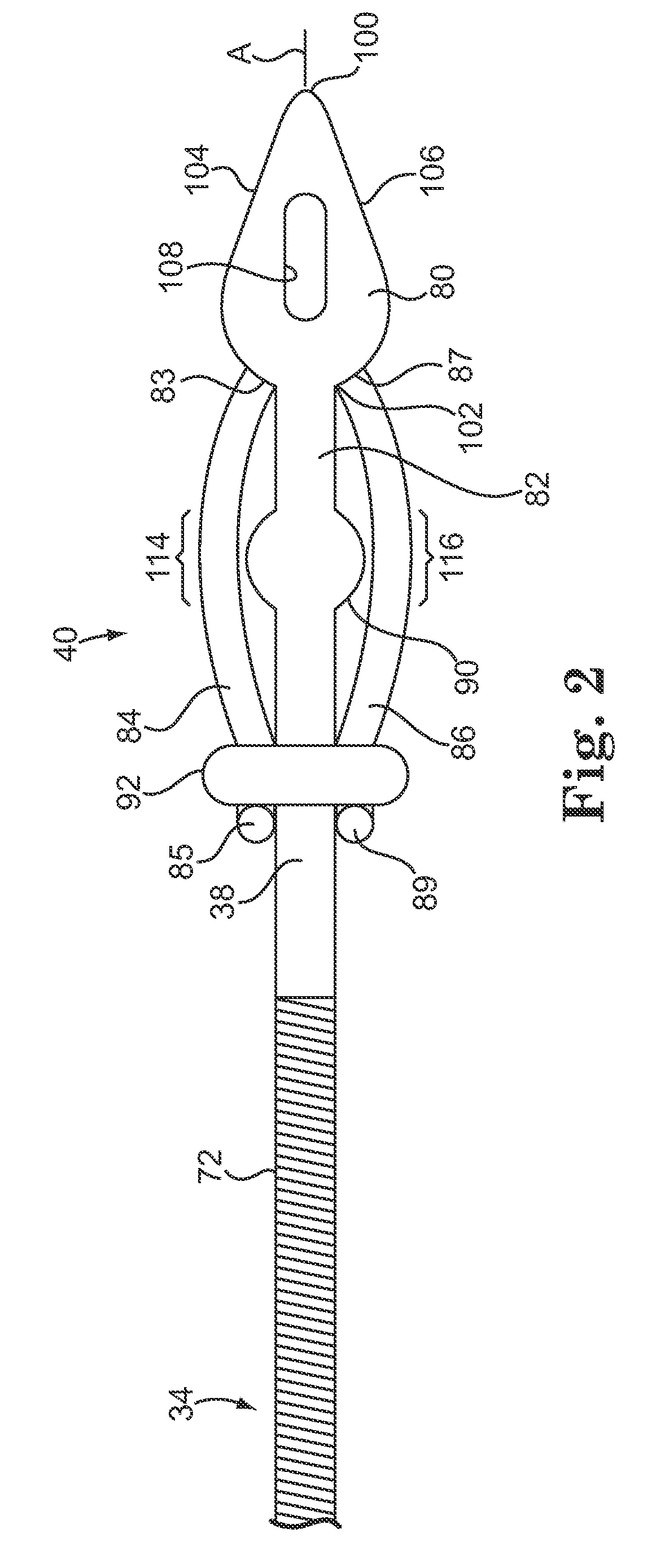
[0016]According to an embodiment of the present invention, a subcutaneously implantable lead is provided that includes a coil disposed along a portion of the lead, and a lead tip coupled to a distal end of the lead. The lead tip includes at least one component that is movable relative to the distal end of the lead and configured to anchor the lead tip in subcutaneous tissue.
[0017]According to an embodiment of the present invention, a method of implanting a lead in a patient, where the lead is attachable to an implantable cardiodefibrillator (ICD), includes subcutaneously advancing a lead tip attached to a distal end of the lead through a surgical incision formed in the patient's skin with a tunneling tool that is removably attached to the lead tip; and activating a movable portion of the lead tip from a proximal end of the lead to fix the distal end of the lead in subcutaneous tissue.
[0018]In this specification, “anchor” means to fix a position of an object relative to tissue to min...
PUM
 Abstract
Description
Claims
Application Information