
Damped Closing Mechanism for automatic Shutting Pull Door

Inactive Publication Date: 2010-02-11
CHUNG SHEEN TECH
View PDF8 Cites 13 Cited by
  • Summary
  • Abstract
  • Description
  • Claims
  • Application Information

AI Technical Summary

Benefits of technology

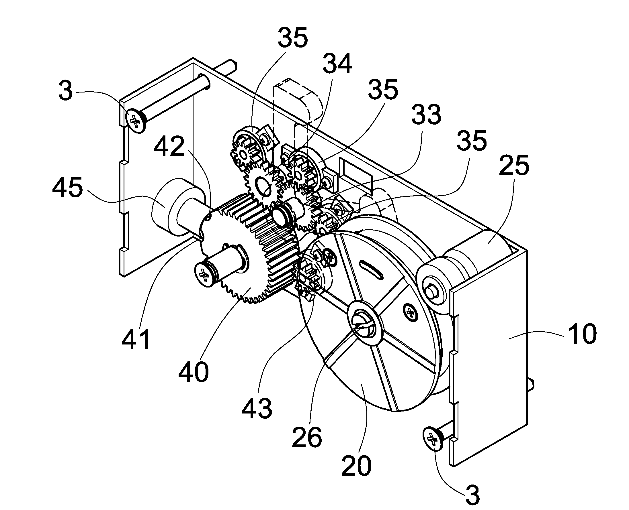
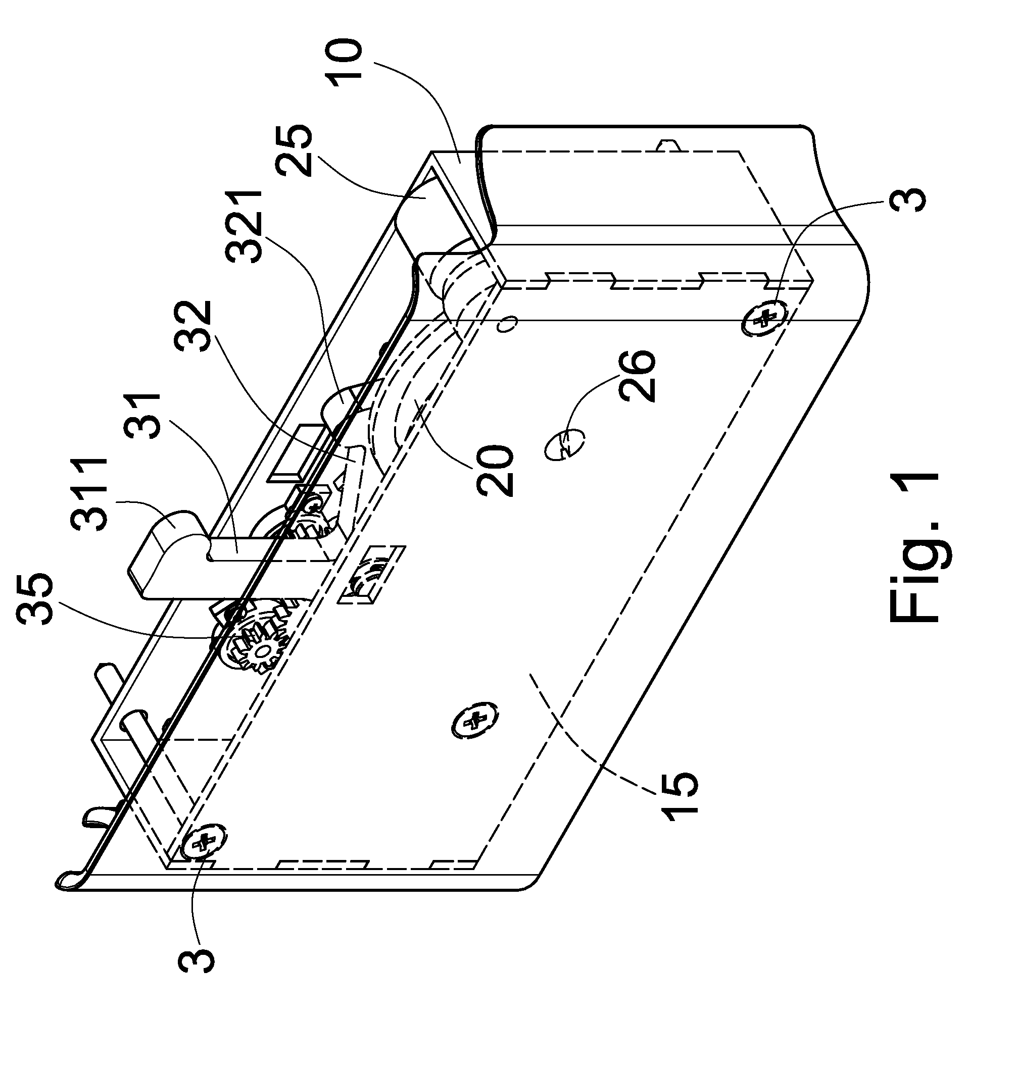
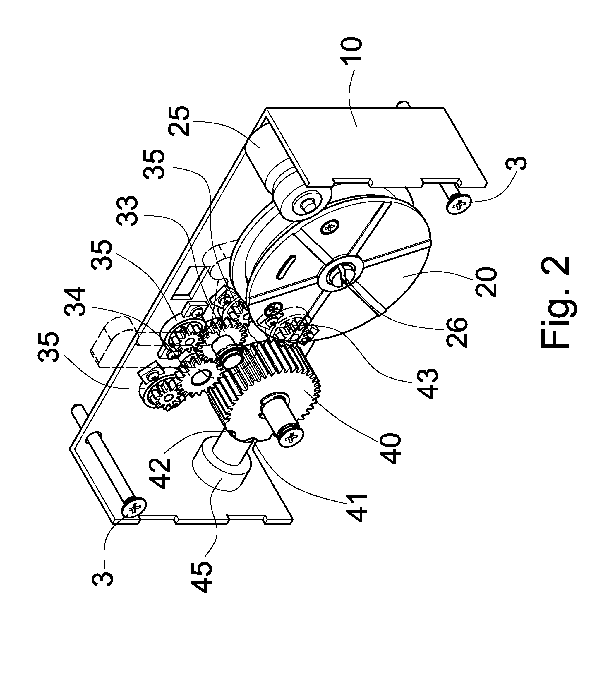
[0007]Accordingly, the object of the present invention is to provide a damped closing mechanism for automatic shutting pull door having a change over device capable of changing the damping effect generated nearby the closing position of the door so as to alleviate colliding speed and impulse of the moving door panel with the door post when shutting without affecting pulling of the door panel before closing.
[0011]The brake gear erected on the base revolves simultaneously with the screw wheel. There is a damping element contained in the brake gear to provide a damping effect. Corresponding with the first and second rocking bars, there are a first and a second positioning dents formed on the brake gear, and a corresponding ball button is provided on the sidewall of the base for the change over device to vary the damping effect of the brake gear.
[0012]With this scheme, when the door panel approaches the door closing position, the change over device actuates the brake gear to vary its position to begin damping so as to alleviate the colliding force and speed of the door panel with the door post yet without affecting pulling back of the door panel before closing.

Problems solved by technology

Take the last one for example, it has successfully eliminated the prior flaw of employing a bulky and awkward rack rail in its automatic closing device, however, it has not been liberated form the conventional disadvantage of lacking damping effect of the helical spring in the closing device that results in failing to lower the travelling speed of the door panel, and causing a loud bumping noise or even disruption of the mechanism or door itself when the door is closed.

Method used


Image

  • Damped Closing Mechanism for automatic Shutting Pull Door
  • Damped Closing Mechanism for automatic Shutting Pull Door
  • Damped Closing Mechanism for automatic Shutting Pull Door

Examples


Embodiment Construction

[0023]Referring to FIG. 1 through FIG. 3, the damped closing mechanism for automatic shutting pull door of the present invention comprises a base 10, a screw wheel 20, a change over device 30, a brake gear 40 and a rope 50.

[0024]Referring further to FIG. 4 through FIG. 6 for understanding more detailed scheme, wherein the base 10 is a shaped frame member having a fence 15 to enclose the bottom and side opening around the base 10 such that an upwardly opened accommodation space is formed between the base 10 and the fence 15.

[0025]The screw wheel 20 is erectly housed in the accommodation space between the base 10 and the fence 15. The screw wheel 20 contains a coil spring (not shown) capable of producing a restoring resilient force when recoiling and making the screw wheel 20 to wind back or extend the rope 50. The screw wheel 20 is provided with an elastic limit member 24 for limiting its revolution and an adjustable mechanism 26 to adjust resilience of the coil spring. The forward ...


PUM


Abstract

In a damped closing mechanism for automatic shutting pull door, a door closing mechanism includes a screw wheel to store restoring force, a change over device and a brake gear to produce a damping effect is integrally combined and equipped on the frame of a moving door panel. The brake gear is to alleviate the actuating force and moving speed of the door panel provided by the screw wheel. The change over device is capable of changing the damping effect of the brake gear to generate nearby the closing position of the door so as to alleviate colliding speed and impulse of the moving door panel with the door post when shutting without affecting the pulling of the door panel before closing.

Description

BACKGROUND OF THE INVENTION[0001]1. Field of the Invention[0002]The present invention relates to the scientific technology of automatic shutting pull door, and in particular, to a damped closing mechanism for automatic shutting pull door in which the automatic closing mechanism can perform a varied damping effect to alleviate the closing force and retard the travelling speed when the moving door panel is about to reach the final shut position so as to avoid the door panel to collide with the door post too forcibly that might result in damaging the door.[0003]2. Description of the Prior Art[0004]For the purpose of performing closing and opening operation of the door efficiently and silently, an automatic door closing mechanism is employed. For example, in order to avoid too loud bumping noise and accidental disruption of a door when closing it too forcibly, an automatic closing mechanism is provided for a revolving or a pull door to alleviate the closing impulse or retard closing spe...

Claims


Application Information

Patent Timeline
IPC IPC(8): E05F3/18E05F3/00
CPCE05F1/16E05F5/003E05Y2201/21Y10T16/27E05Y2201/41E05Y2201/412Y10T16/293E05Y2201/25
Inventor CHIANG, CHOU-CHIH
Owner CHUNG SHEEN TECH
Learn More