Yarn tensioning mechanism for spinning

A tensioning mechanism and yarn technology, applied in the direction of conveying filamentous materials, thin material handling, transportation and packaging, etc., can solve the problems of high tensioning strength, loose yarns, affecting yarn spinning, etc. high intensity effect

Active Publication Date: 2020-02-21
安徽双盈纺织有限公司
View PDF9 Cites 9 Cited by
  • Summary
  • Abstract
  • Description
  • Claims
  • Application Information

AI Technical Summary

Problems solved by technology

[0002] Textile machine, also known as textile machine, loom, cotton spinning machine, etc., textile machine is the full name of a tool that processes raw materials such as thread, silk, and hemp into silk and then weaves them into cloth; at present, textile machines are usually used in conjunction with yarn guide devices. Some yarns are in the process of conducting wires, and it is difficult to maintain the tension during the yarn transmission process. If the tension strength is weak, the yarn will be loose and entangled. If the tension strength is high, the yarn will eventually fail smooth, so that the yarn is very easy to be torn during the guiding process, which affects the yarn weaving, so a yarn tensioning mechanism for textile is designed here to solve the above problems

Method used


Image

  • Yarn tensioning mechanism for spinning
  • Yarn tensioning mechanism for spinning
  • Yarn tensioning mechanism for spinning

Examples


Embodiment 1

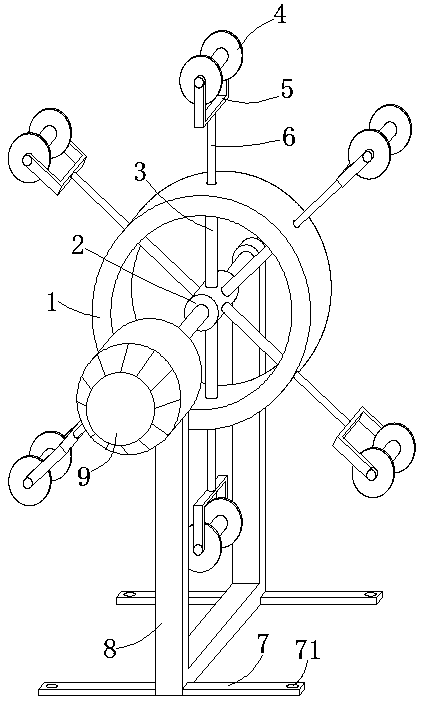
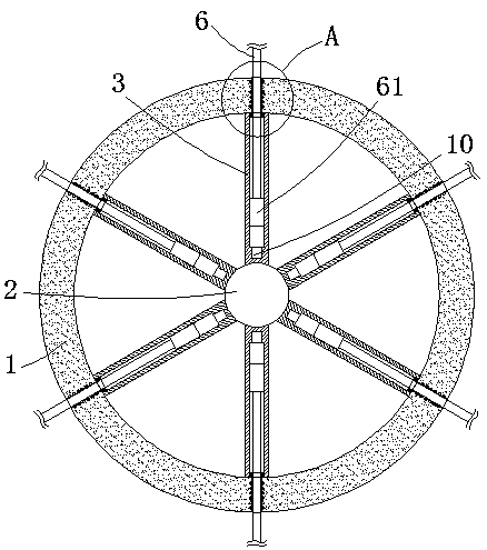
[0027] see Figure 1-3 , the present embodiment provides a yarn tensioning mechanism for textiles, comprising a mounting bracket 8 and a guide roller 1, the mounting bracket 8 is a U-shaped structure, the inner cavity of the guide roller 1 is a hollow structure, and the inner cavity of the guide roller 1 There are several hollow sleeves 3 that are evenly spaced in a ring and are radially welded. The connecting shafts 2 are fixedly welded between the tips of the several hollow sleeves 3. The side walls on both sides of the connecting shaft 2 are welded with joints The connecting rods distributed in the axial direction of the shaft 2, the guide roller 1 is rotationally connected with the top of the inner front and rear side walls of the mounting bracket 8 through two connecting rods, and the end of each hollow sleeve 3 away from the connecting shaft 2 is extended to the end of the guide roller 1 The side wall of the inner ring and the radial side wall of the guide roller 1 are p...

Embodiment 2

[0034] see Figure 1-3 , made further improvement on the basis of embodiment 1:

[0035] The outer wall of each I-shaped yarn guide wheel 4 is sleeved with anti-slip rubber sleeves, and the sliding friction force when the I-shaped yarn guide wheels 4 leads are enhanced to prevent skidding by setting the anti-slip rubber sleeves.

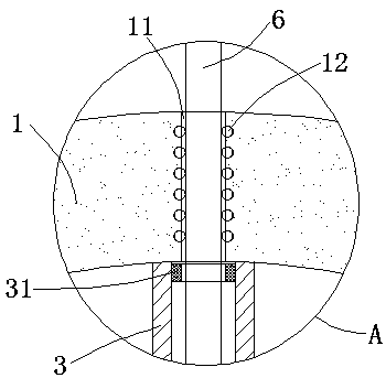
[0036] The inner cavity side wall of each sliding insertion hole 11 is embedded with a number of steel balls 12 that are evenly spaced and are rotatably fitted to the outer wall of the extension rod 6 . Sliding resistance when rod 6 slides.

[0037] The major diameter of the inner cavity of each sliding insertion hole 11 is equal to 0.8 times of the major diameter of the inner cavity of each hollow sleeve 3, which prevents the limit magnet block 61 from crossing the inner cavity of the sliding insertion hole 11, thereby preventing the extension rod 6 from breaking away The inner cavity of the hollow sleeve 3.

[0038] Mounting plates 7 are horizon...


PUM


Abstract

The invention discloses a yarn tensioning mechanism for spinning. The mechanism comprises a mounting support and a guide roller. Multiple hollow sleeves annularly and evenly distributed at intervals are radially welded to an inner cavity of the guide roller, connection shafts are fixedly welded between the tip ends of the hollow sleeves, and the guide roller is rotatably connected with the top ends of the front and rear side walls of the inner side of the mounting support through two connection rods. The end, away from a connection shaft, of each hollow sleeve extends to the inner side of theinner circle of the guide roller, the radial side wall of the guide roller is provided with multiple slidable insertion holes annularly and evenly distributed at intervals, an extension rod is slidingly inserted in an inner cavity of each slidable insertion hole, each extension rod extends into an inner cavity of the corresponding hollow sleeve, and the tip end of each extension rod is provided with an I-shaped yarn guide wheel freely rotating on a corresponding mounting rack through the corresponding mounting rack. According to the yarn tensioning mechanism for spinning, the situations are avoided that due to weak tensioning strength, yarn is loose and is wound in disorder, and due to high tensioning strength, the yarn is extremely easily broken off in the guide process.

Description

technical field [0001] The invention relates to the technical field related to textiles, in particular to a yarn tensioning mechanism for textiles. Background technique [0002] Textile machine, also known as textile machine, loom, cotton spinning machine, etc., textile machine is the full name of a tool that processes raw materials such as thread, silk, and hemp into silk and then weaves them into cloth; at present, textile machines are usually used in conjunction with yarn guide devices. Some yarns are in the process of conducting wires, and it is difficult to maintain the tension during the yarn transmission process. If the tension strength is weak, the yarn will be loose and entangled. If the tension strength is high, the yarn will eventually fail Smooth, so that the yarn is very easy to be torn during the guiding process, which affects the yarn weaving. Therefore, a yarn tensioning mechanism for textile is designed here to solve the above problems. Contents of the inv...

Claims


Application Information

Patent Timeline
Patent Type & Authority Applications(China)
IPC IPC(8): B65H57/14B65H59/10B65H57/26
CPCB65H57/14B65H57/26B65H59/10B65H2701/31
Inventor 刘化杰刘云雷李小辉
Owner 安徽双盈纺织有限公司
Why Eureka
Try Eureka