

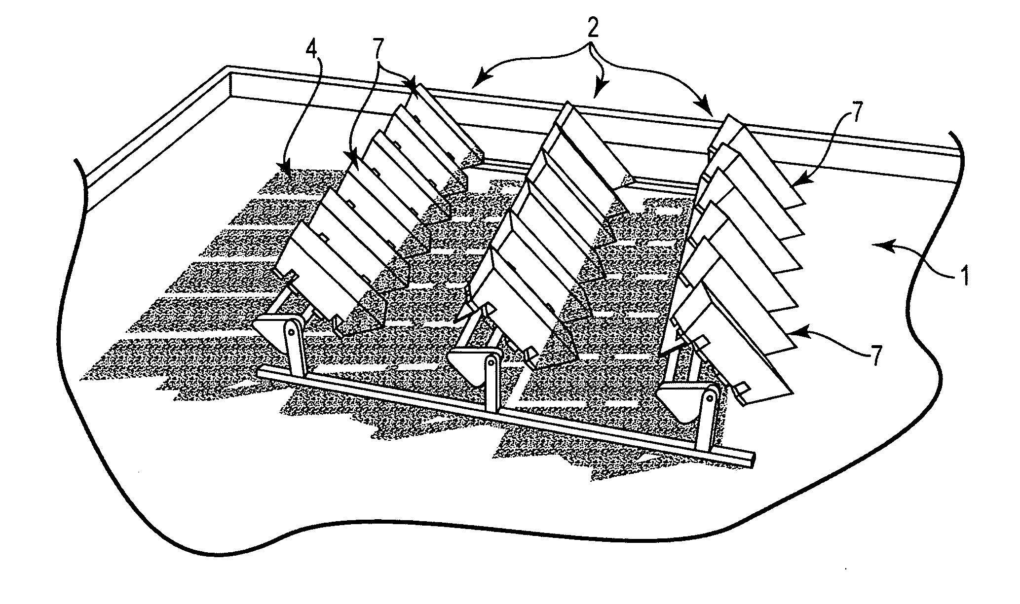
Solar systems that include one or more shade-tolerant wiring schemes
a solar panel and wiring scheme technology, applied in solar heat systems, pv power plants, lighting and heating apparatus, etc., can solve the problems of not being able to make efficient use of space, solar panels are not particularly tolerant of shadows, and tend to cast shadows, etc., and achieve the effect of simple structure and simple geometry
- Summary
- Abstract
- Description
- Claims
- Application Information
AI Technical Summary
Benefits of technology
Problems solved by technology
Method used
Image

Examples
Embodiment Construction
[0077]The embodiments of the present invention described below are not intended to be exhaustive or to limit the invention to the precise forms disclosed in the following detailed description. Rather the embodiments are chosen and described so that others skilled in the art may appreciate and understand the principles and practices of the present invention.
[0078]In particular, while a preferred embodiment shown is a concentrating photovoltaic module, the methods and techniques taught by the invention apply equally well to ordinary solar panels that do not make use of concentration; the invention applies in any case where the (concentrating or not) photovoltaic module includes subapertures whose light is respectively collected on individual solar cells or groups of solar cells.
[0079]In the embodiments described below, the same reference characters are used to describe features that are the same among the embodiments.
[0080]As used herein, a sub-aperture generally has a one to one corr...
PUM
 Abstract
Description
Claims
Application Information