Eureka AIR delivers breakthrough ideas for toughest innovation challenges, trusted by R&D personnel around the world.

Hyper-surface wind generator

a wind generator and hyper-surface technology, applied in the direction of electric generator control, machines/engines, mechanical equipment, etc., can solve the problems of large construction and large construction requirements for wind generators larger than 2,000 watts, and the inability to produce enough energy to meet the needs of large-scale construction, and achieve the effect of suppressing vibration in the undesired direction

Inactive Publication Date: 2010-02-11
INFINITE WIND ENERGY
View PDF99 Cites 7 Cited by
  • Summary
  • Abstract
  • Description
  • Claims
  • Application Information

AI Technical Summary

Benefits of technology

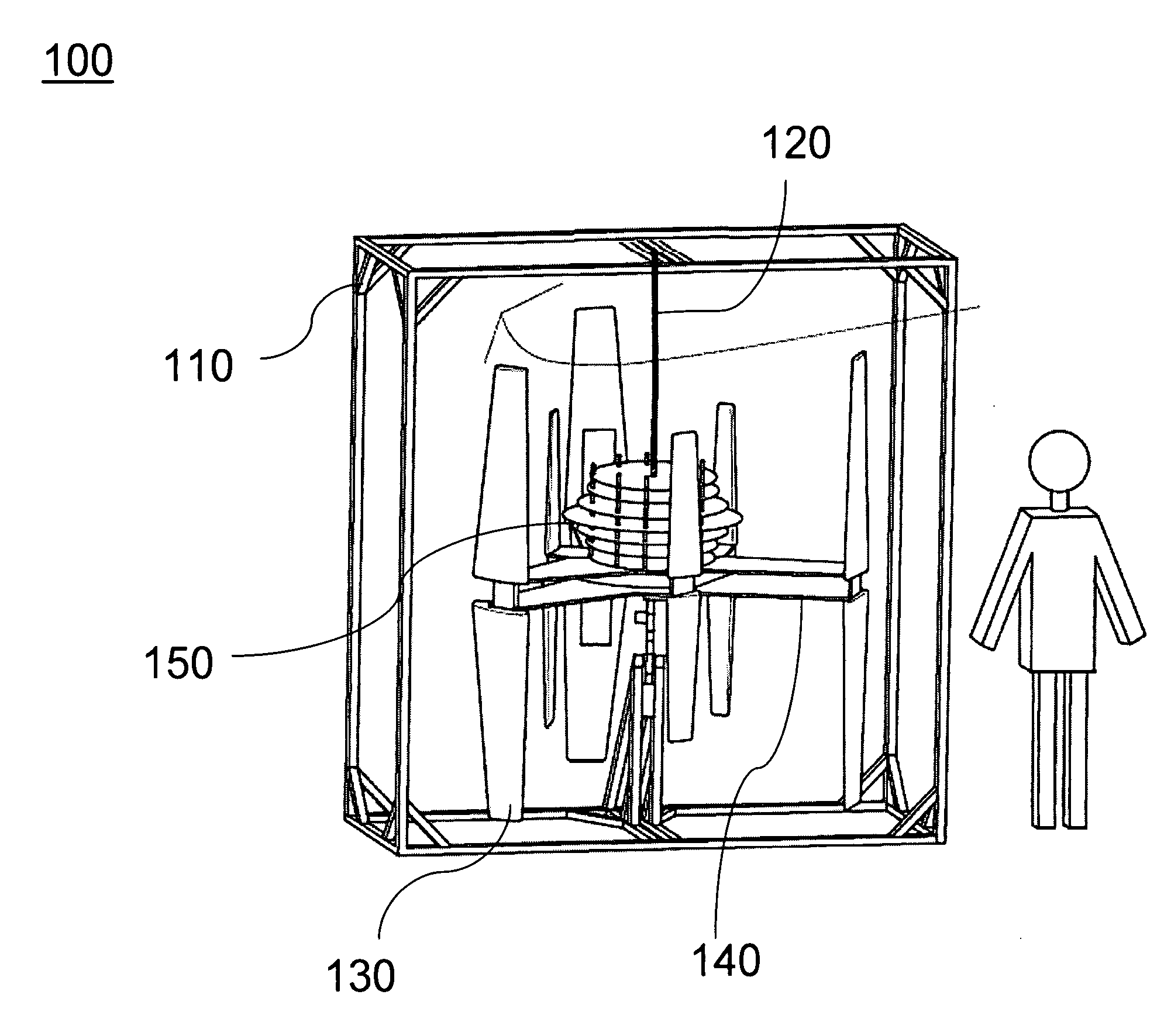
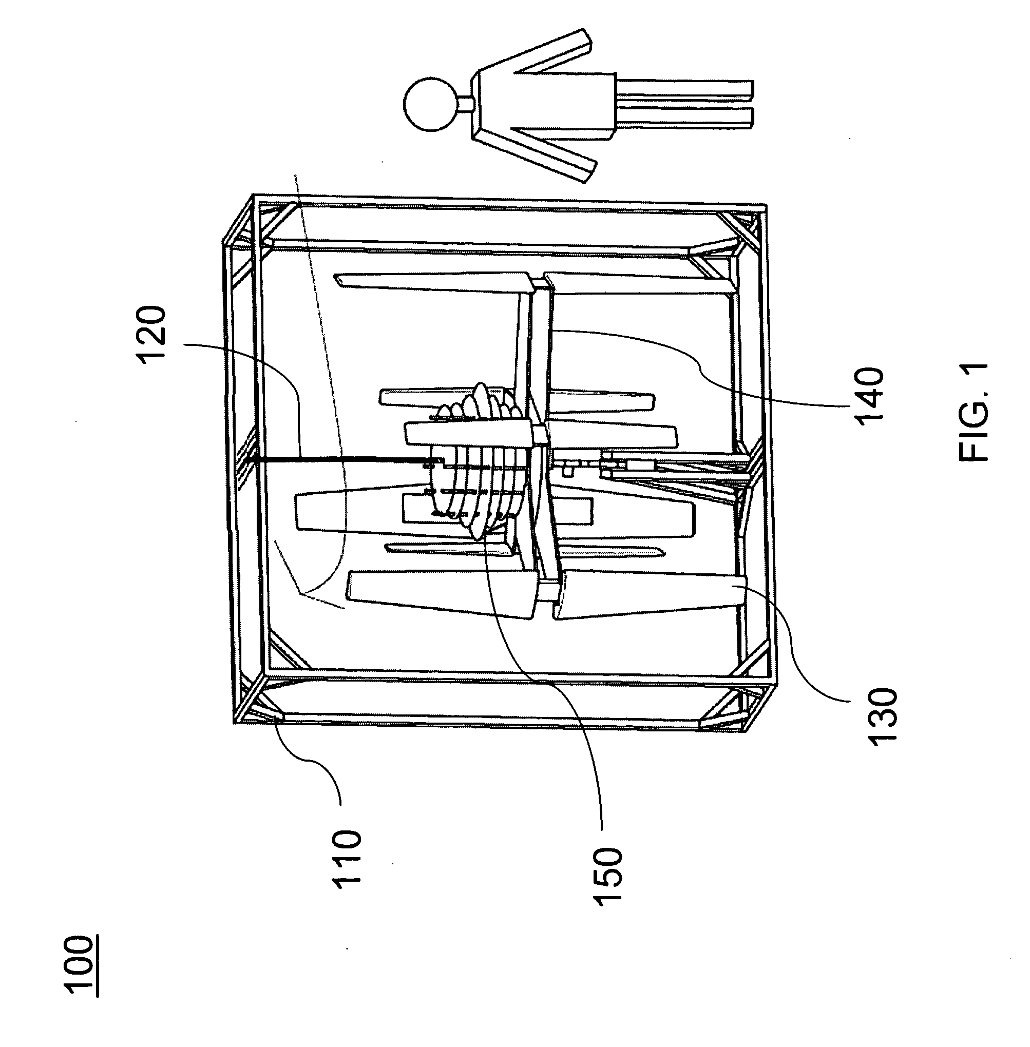
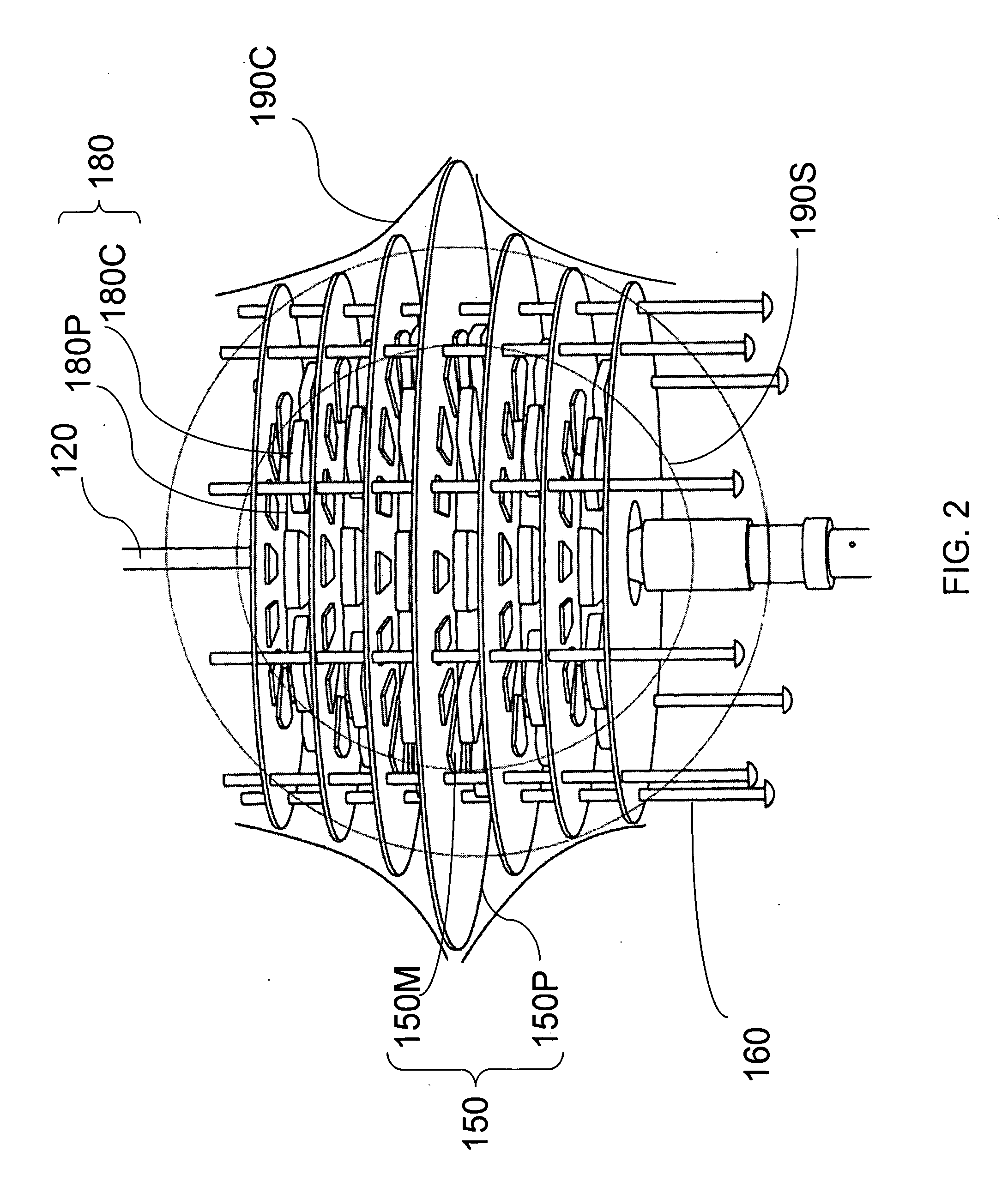
"The present invention is a stackable hyper-surface wind generator that solves problems in related art. It is compact, generates a lot of energy, and has high efficiency. It also has a counter-rotation mechanism and suppresses vibration in undesired directions. The generator includes stator plates, rotor plates, and blades that induce electricity in coils on the stator plates when rotated. The rotor plates and stator plates can be arranged co-axially with a shaft, and the blades can be formed to enable counter-rotation. Overall, the invention provides a reliable wind generator with improved performance."

Problems solved by technology

However, there are limitations on how much energy a wind generator can produce.
For example, building wind generators of bigger than 2,000 Watts is a major project requiring very large construction.
Conventional wind generators that are large are unstable and inefficient.

Method used


Image

  • Hyper-surface wind generator
  • Hyper-surface wind generator
  • Hyper-surface wind generator

Examples


Embodiment Construction

[0037]Reference will now be made in detail to the embodiments of the present invention, examples of which are illustrated in the accompanying drawings.

[0038]When an inductive element, i.e., a wire or a coil, is placed within a magnetic field and when the inductive element rotates within the magnetic field, current is induced within the inductive element. The magnitude of the induced current depends on the strength of the magnetic field, the length of the inductive element, and the speed with which the inductive element moves within the magnetic field. The strength of the magnetic field can be enhanced by using magnets with higher magnetization. However, there are limitations on the strength of the magnets due to intrinsic material properties. Accordingly, in accordance with aspects of the present invention, efficiency of the wind generator is enhanced by changing the structure and design of the wind generator. In an exemplary embodiment of the present invention, a plurality of rotor...


PUM


Abstract

An electric generator capable of generating electric power using kinetic energy of wind includes a first plurality of rotor plates, a second plurality of rotor plates, and a first plurality of blades capable of driving the first plurality of rotor plates, a second plurality of blades being formed to enable counter-rotation with respect to the first plurality of blades, wherein rotation of the first plurality of rotor plates relative to the second plurality of rotor plates induces electricity in a plurality of coils disposed on the second plurality of rotor plates, and wherein at least one of the first and second plurality of rotor plates are arranged co-axially with the shaft such that respective radii of the at least one of the first and second plurality of rotor plates are varied along the axial direction.

Description

BACKGROUND OF THE INVENTION[0001]1. Field of the Invention[0002]The present invention relates to power generators, and more particularly, to stackable wind power generators.[0003]2. Discussion of the Related Art[0004]Wind generators create electricity by converting kinetic energies of wind into electric energy. Wind powered generators have great advantages over other generators. Wind generators are not only environmentally safe but also economically sound and sustainable. Unlike fuel generators, there is no need to purchase fuel. The source of energy is wind, which can be obtained in nature. Because wind has kinetic energy to produce electricity, there is no byproduct produced. Accordingly, there is almost zero pollution.[0005]A wind generator converts mechanical energy from the wind into electrical energy using electromagnetic induction. Small wind generators that create 700-1,000 Watts can be easily made. However, there are limitations on how much energy a wind generator can produ...

Claims


Application Information

Patent Timeline
Patent Type & Authority Applications(United States)
IPC IPC(8): F03D9/00
CPCY02E10/72F03D9/00F03D3/02F03D9/25F03D15/20
Inventor KIM, CHONG-KYU
Owner INFINITE WIND ENERGY
Why Eureka
Eureka Blog
Learn More