Engine with centrifugal clutch

a centrifugal clutch and clutch technology, which is applied in the direction of mechanical actuated clutches, machines/engines, couplings, etc., can solve the problems of increasing the rotational resistance due to the oil, increasing the power loss of the crankshaft, and thus not being able to supply oil, so as to reduce the friction resistance or the like and reduce the loss of power transmission

Active Publication Date: 2010-07-01
KAWASAKI MOTORS LTD
View PDF3 Cites 0 Cited by
  • Summary
  • Abstract
  • Description
  • Claims
  • Application Information

AI Technical Summary

Benefits of technology

[0019]With the above configuration, out of the plurality of journal portions of the crankshaft, the centrifugal clutch is mounted at an end of the crankshaft supported by the ball bearing or the roller bearing and is coupled to the d

Problems solved by technology

In the above configuration according to the prior art, however, when the clutch housing is excessively immersed in the oil in order to improve a cooling effect, rotational resistance due to th

Method used


Image

  • Engine with centrifugal clutch
  • Engine with centrifugal clutch
  • Engine with centrifugal clutch

Examples


Embodiment Construction

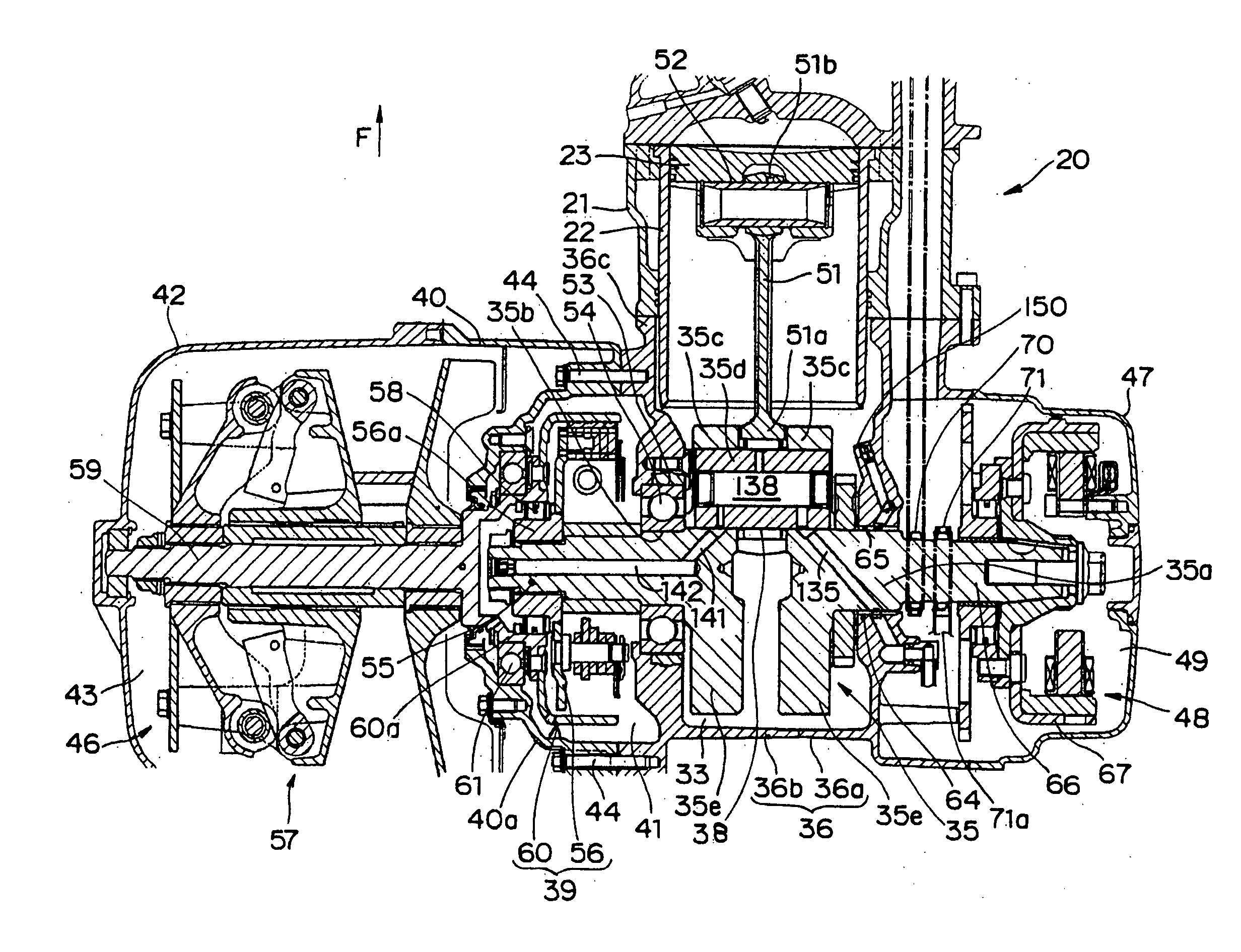
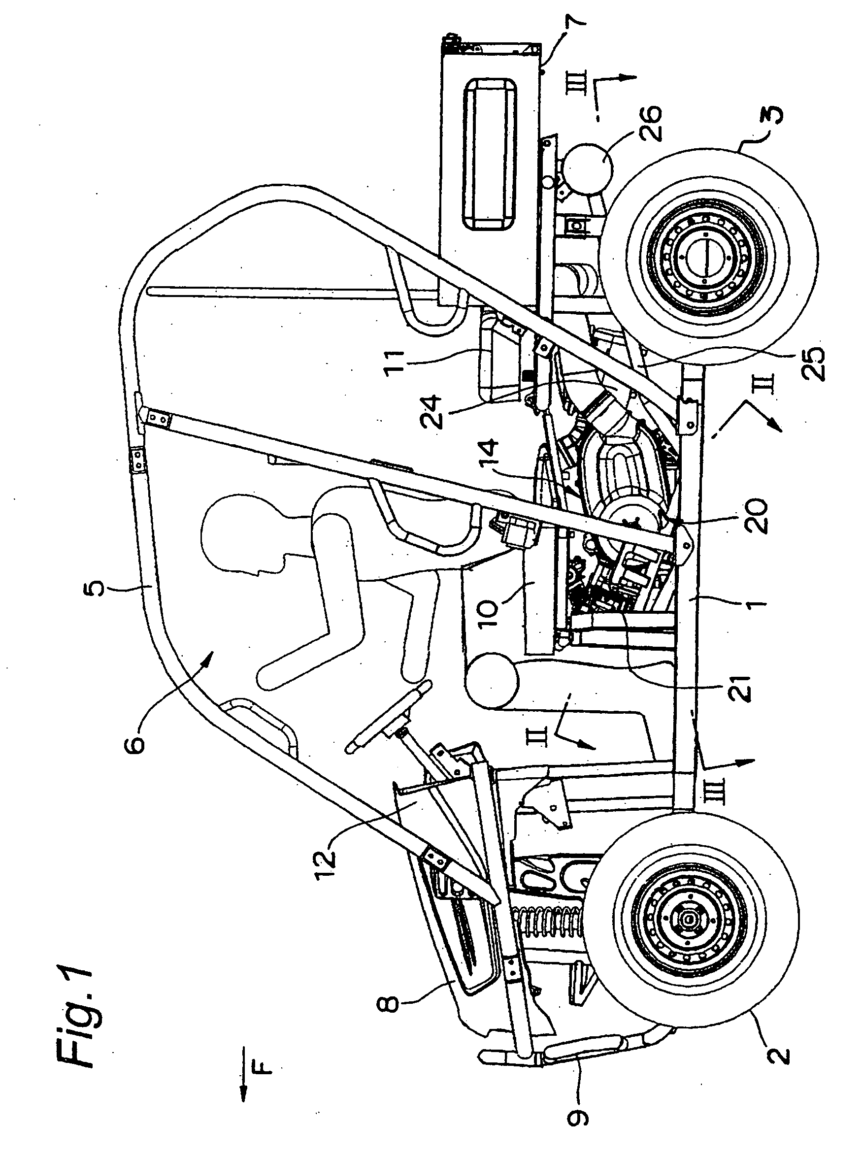
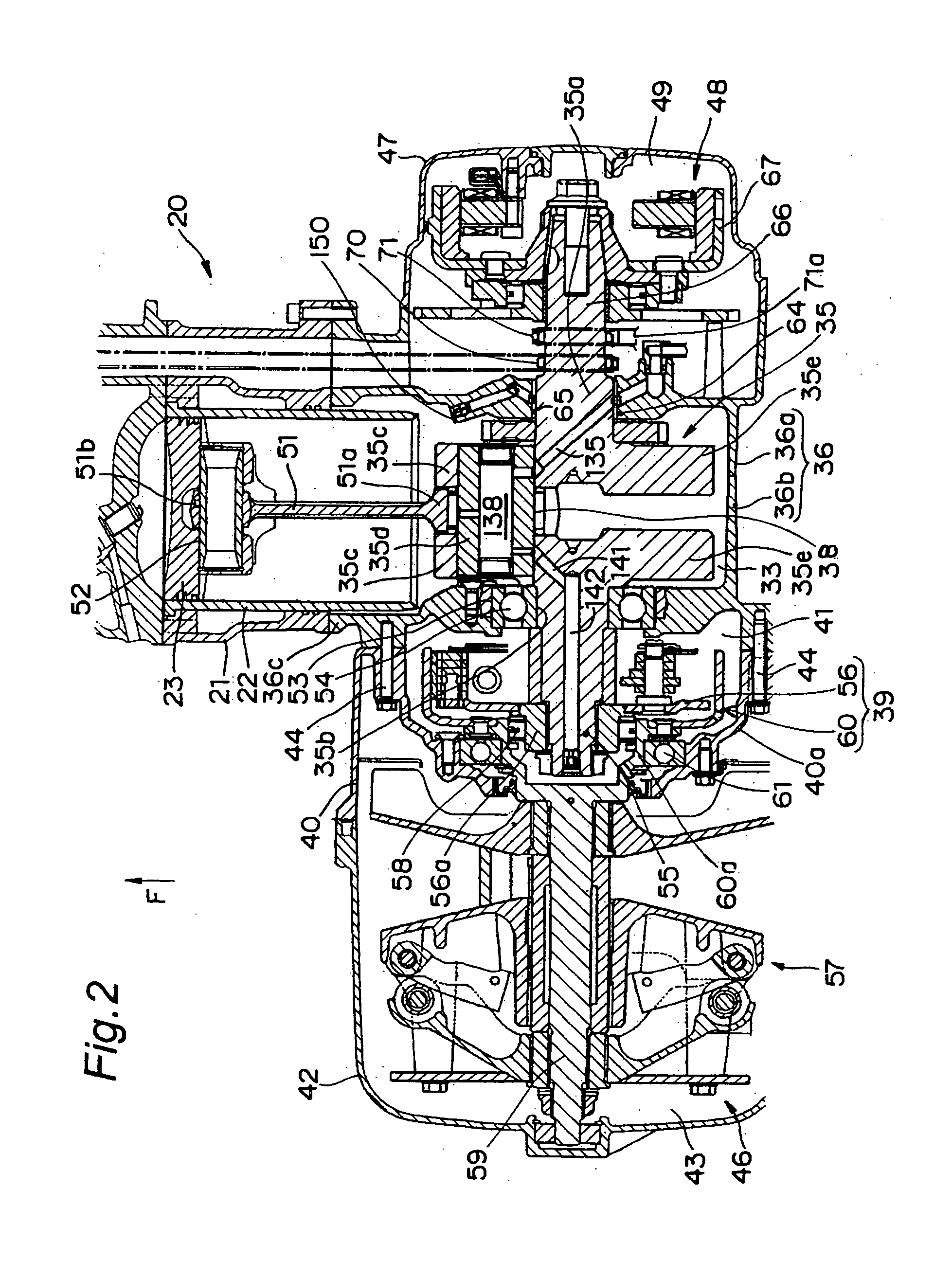
[0028]FIGS. 1 to 6 illustrate a first embodiment of an engine according to the present invention. An embodiment of the present invention will be described with reference to these drawings.

[0029]FIG. 1 is a left side view, partially broken away, of a small four-wheeled vehicle for irregular grounds (a so-called utility vehicle) on which an engine with a centrifugal clutch according to the present invention is mounted. In FIG. 1, the four-wheeled vehicle has a pair of right and left front wheels 2 in a front portion of a body frame 1, a pair of right and left rear wheels 3 in a rear portion of the body frame 1, a cabin 6 surrounded by a cabin frame 5 between the front wheels 2 and the rear wheels 3, a loading space 7 rearwardly of the cabin 6, a bonnet 8 and a bumper 9 forwardly of the cabin 6, and fenders over wheels 2 and 3.

[0030]A bench type front seat 10 is installed in a front half portion in the cabin 6. A folding, bench type rear seat 11 is installed in a rear half portion in t...


PUM


Abstract

The present invention provides an engine with a centrifugal clutch which can efficiently cool and lubricate the centrifugal clutch. The engine according to the present invention supports a pair of journal portions of a crankshaft by a bearing such as a ball bearing, a roller bearing, or the like, as well as a bearing metal. There is provided first oil supplying means formed in the crankshaft. The first oil supplying means has an oil passage for the first oil supplying means which is communicated with a main oil passage through an oil hole formed in the bearing metal and extends through a fitting portion of a crankpin to reach the centrifugal clutch.

Description

BACKGROUND OF THE INVENTION[0001]1. Field of the Invention[0002]The present invention relates to an engine with a centrifugal clutch. More specifically, the present invention relates to an engine which has a centrifugal clutch at an end of a crankshaft and an oil supplying configuration which supplies cooling and lubricating oil to the centrifugal clutch.[0003]2. Description of the Related Art[0004]A centrifugal clutch provided on a crankshaft of an engine typically has an inner member fixed to the crankshaft and a clutch housing fixed to a driven rotational member. The inner member has a centrifugal weight moved radially outward by a centrifugal force generated by rotation of the crankshaft. The centrifugal weight has a clutch shoe made of a friction member. The clutch housing has a cylindrical portion which is located radially outside and opposite the centrifugal weight and with which the clutch shoe of the centrifugal weight can be brought into contact. Such a centrifugal clutch ...

Claims


Application Information

Patent Timeline
IPC IPC(8): F16D43/04
CPCF16D43/18F16D2300/021F16D2300/06
Inventor TAKANO, KIYOHITO
Owner KAWASAKI MOTORS LTD
Why Eureka
Try Eureka