Eureka AIR delivers breakthrough ideas for toughest innovation challenges, trusted by R&D personnel around the world.

Voltage detecting circuit and voltage detecting method

Inactive Publication Date: 2010-02-11
NOVATEK MICROELECTRONICS CORP
View PDF12 Cites 1 Cited by
  • Summary
  • Abstract
  • Description
  • Claims
  • Application Information

AI Technical Summary

Benefits of technology

[0012]Accordingly, the present invention is directed to a voltage detecting circuit and a voltage detecting method, which do not use a band-gap circuit, and improve the tolerance to processes in voltage detection.

Problems solved by technology

However, the detected voltage will have severe shift with the change of processes when the band-gap circuit is not used.
The conventional circuit has a disadvantage that the trigger voltage will vary with the critical voltage Vth and the characteristic parameter β of the semiconductor devices.
The critical voltage Vth and the characteristic parameter β may be different due to different processes, thus causing variances in the detection results.

Method used


Image

  • Voltage detecting circuit and voltage detecting method
  • Voltage detecting circuit and voltage detecting method
  • Voltage detecting circuit and voltage detecting method

Examples


Embodiment Construction

[0039]Reference will now be made in detail to the present embodiments of the invention, examples of which are illustrated in the accompanying drawings. Wherever possible, the same reference numbers are used in the drawings and the description to refer to the same or like parts.

[0040]The voltage detecting circuit and the voltage detecting method of the present invention at least can improve the tolerance to processes in voltage detection without using a band-gap circuit. The present invention is illustrated below with the following embodiments, but is not limited to the embodiments.

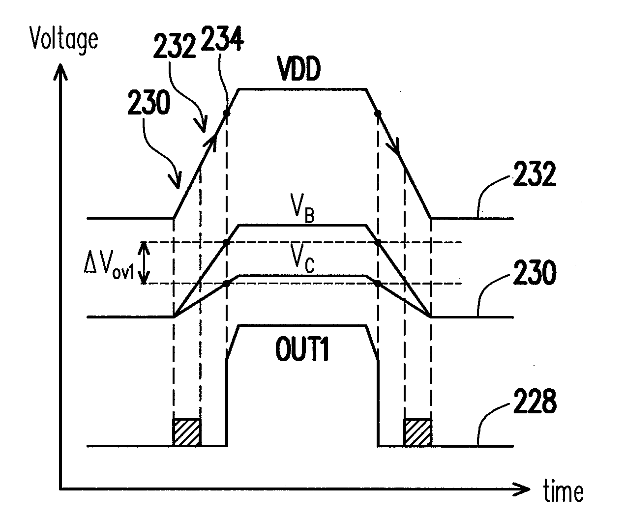
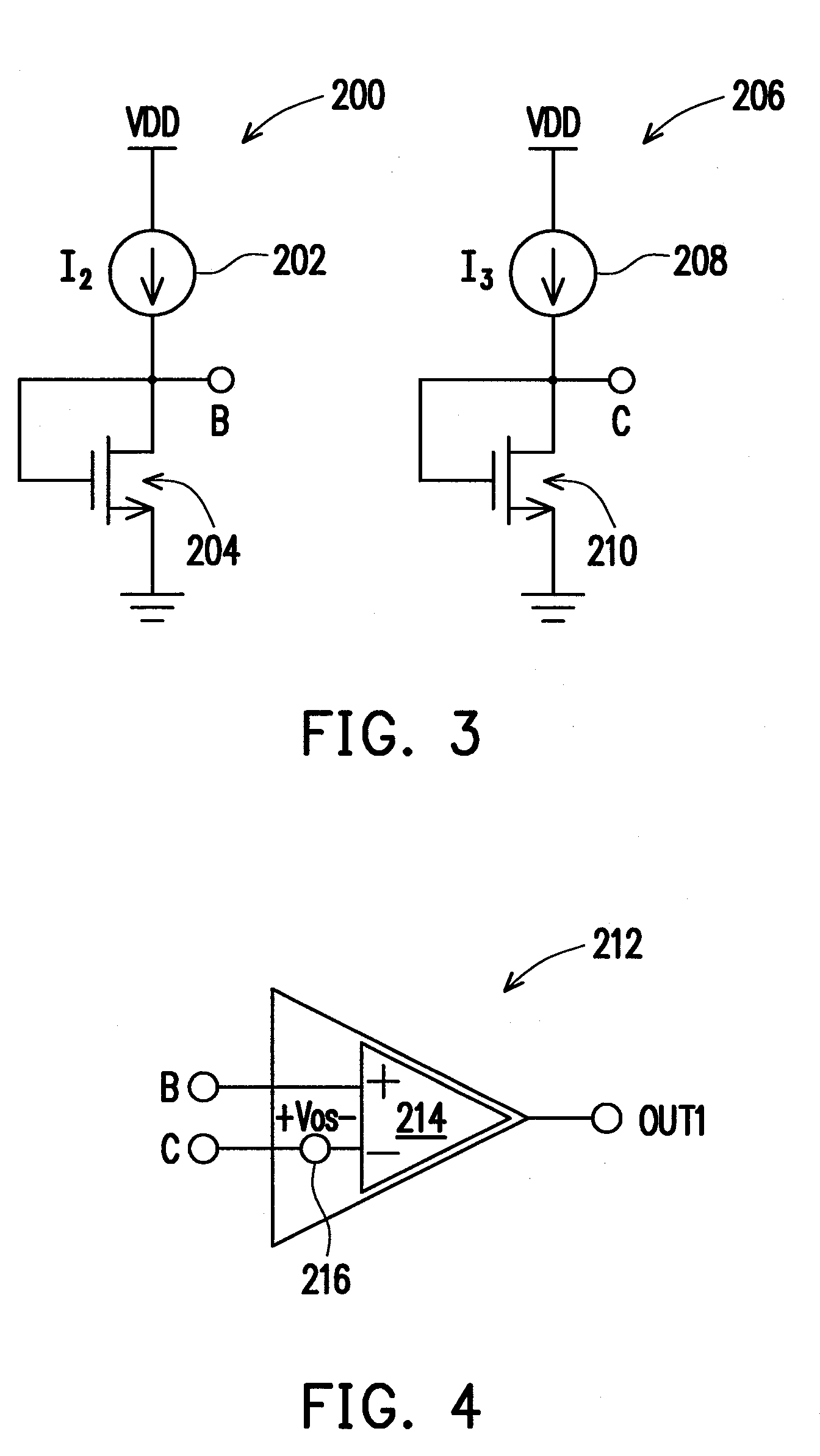
[0041]FIG. 3 is a schematic circuit diagram of producing a detection voltage by using variance of difference between two voltages at a front end of a voltage detecting circuit according to an embodiment of the present invention. Referring to FIG. 3, two circuit routes 200, 206 of the present invention produce a voltage respectively for analysis, thus solving the problem of unstable detection caused by the ...


PUM


Abstract

Voltage detecting circuit for detecting a voltage state of a voltage source includes a first route, a second route and a comparator. First route is between a voltage source and a ground voltage, having a first current source and a first MOS resistor, connected in series at a first node with outputting a first voltage. Second route is between the voltage source and the ground voltage, having a second current source and a second MOS resistor, connected in series at a second node with outputting a second voltage. The comparator receives the first voltage and the second voltage and outputs the voltage state. The comparator includes a current offset circuit for producing an offset voltage to the second voltage. A voltage comparing unit compares the first voltage and the second voltage with offset by a voltage difference, and outputs the voltage state according to variance of the voltage difference.

Description

CROSS-REFERENCE TO RELATED APPLICATION[0001]This application claims the priority benefit of Taiwan application serial no. 97130391, filed Aug. 8, 2008. The entirety of the above-mentioned patent application is hereby incorporated by reference herein and made a part of this specification.BACKGROUND OF THE INVENTION[0002]1. Field of the Invention[0003]The present invention generally relates to voltage detecting technology, in particular, to a voltage detecting circuit and a voltage detecting method at least capable of solving the problem of unstable detection caused by process difference.[0004]2. Description of Related Art[0005]A common integrated circuit uses a voltage source, for example, a VDD. However, during the operation of the circuit, the voltage source will be turned on and off frequently, so for some circuits, the voltage state of the voltage source must be detected accurately.[0006]Conventional voltage detecting circuits have various designs. A complex circuit design uses a...

Claims


Application Information

Patent Timeline
IPC IPC(8): G01R19/00
CPCG01R19/16552
Inventor LIN, CHIA-HUNG
Owner NOVATEK MICROELECTRONICS CORP
Why Eureka
Eureka Blog
Learn More