
Sealed circuit breaker

Active Publication Date: 2010-02-11
APPLETON GRP
View PDF54 Cites 24 Cited by
  • Summary
  • Abstract
  • Description
  • Claims
  • Application Information

AI Technical Summary

Benefits of technology

[0007]The present application provides a sealed electrical enclosure for use in hazardous locations for enclosing circuit breakers or other electrical components comprising a bottom housing and a top housing positioned thereabove; a labyrinth seal or joint being formed between the bottom housing and the top housing; the bottom housing adapted to receive a plurality of circuit breakers or other electrical components; and a first metal bus extending from a point internal to the bottom housing through a first end wall to a point external to the bottom housing; and a second metal bus extending from a point internal to the bottom housing through a second end wall to a point ex

Problems solved by technology

A drawback of this arrangement is that the cast iron enclosures are heavy and cumbersome.
Furthermore, it can be time consuming and laborious to remove the often extensive number of bolts from the cast metal housing to access the circuit breakers within.
Thus, replacing circuit breakers using enclosures with this construction can be time consuming and costly.
A drawback to this methodology is that it is more costly to replace each separately sealed flame proof circuit breakers than it is to replace non-flame proof circuit breakers.

Method used


Image

  • Sealed circuit breaker
  • Sealed circuit breaker
  • Sealed circuit breaker

Examples


Embodiment Construction

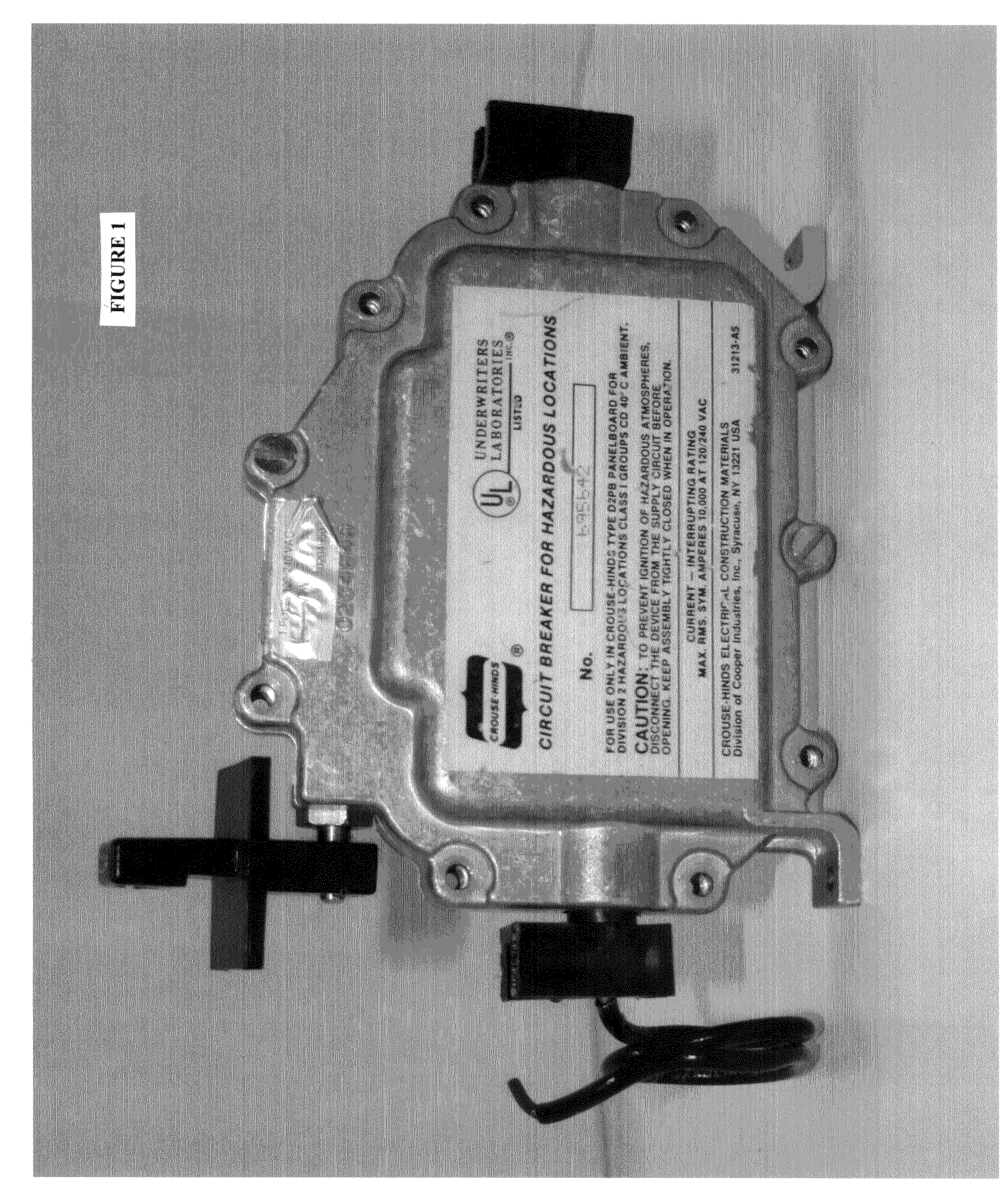
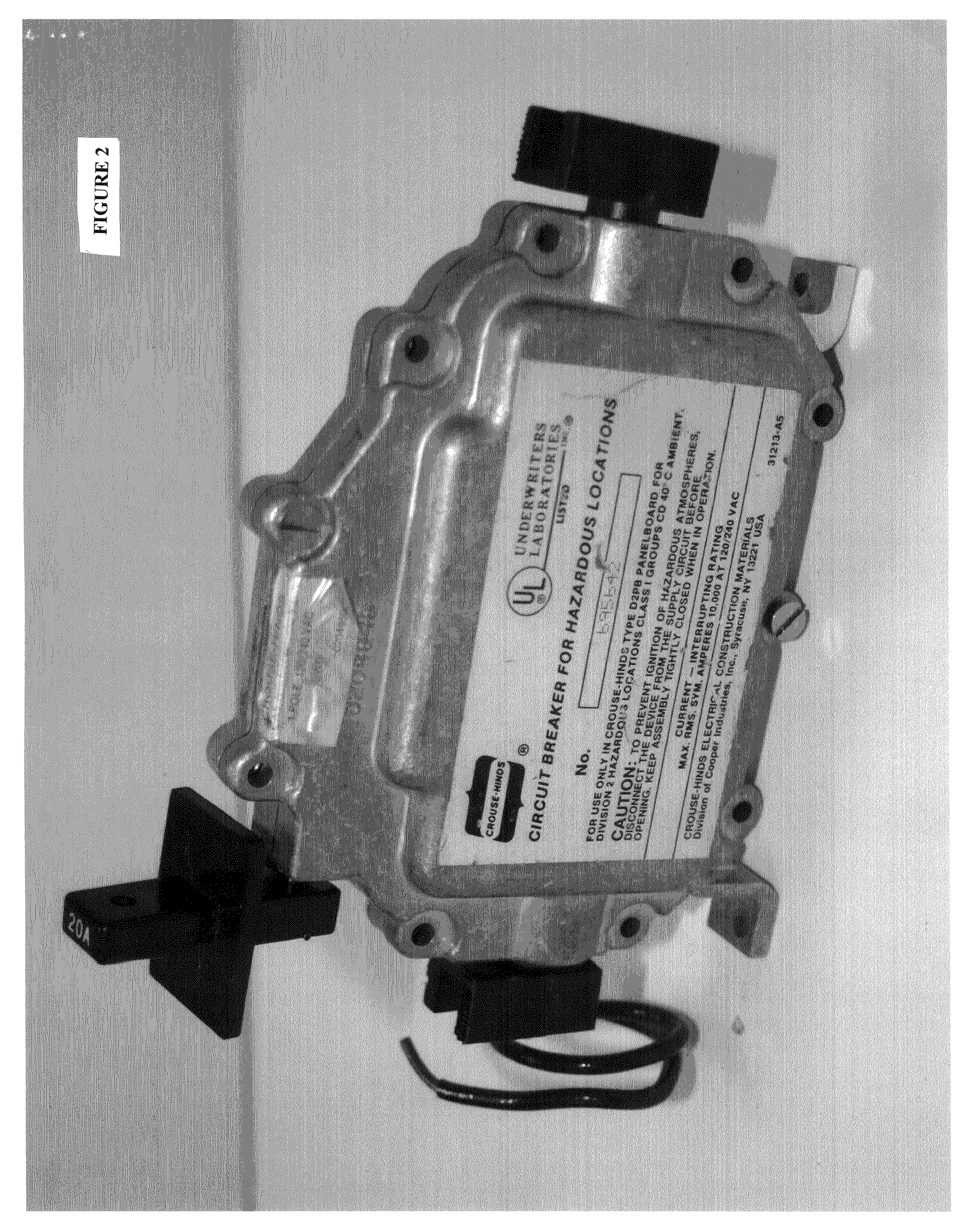
[0026]Referring to FIG. 1, a perspective view of sealed electrical enclosure 10 is shown having bottom housing 12 and top housing 14, with top housing 14 being removably secured to bottom housing 12 using bolts 22. Of course, it is not required to use bolts, but any other suitable means of removably securing top housing 14 to bottom housing 12 could be used such as clips, screws, clamps, latches, etc. Preferably bottom housing 12 and top housing 14 are comprised of hard non-conductive material such as a plastic or composite material, most preferably Solvay IXEF 1022 or Ryton R-4.

[0027]Sealed electrical enclosure 10 further includes an actuating mechanism 20 that allows for the manipulation of the switches of circuit breakers or other electrical components positioned within the enclosure 10. The actuating mechanism 20 provides for linear actuation, although rotary actuation could be used as well. Enclosure 10 may be used to house various types of circuit breakers and other electrical...


PUM


Abstract

A sealed electrical enclosure used in hazardous locations for enclosing circuit breakers having a bottom housing and a top housing with a labyrinth seal or joint formed therebetween, the bottom housing adapted to receive one or more circuit breakers, a first metal bus extending from a point internal to the bottom housing through a first end wall to a point external thereto, and a second metal bus extending from a point internal to the bottom housing through a second end wall to a point external to thereto, where the first and second metal buses are adapted to contact first and second electrical terminals of a circuit breaker when placed within the bottom housing, and a first vent positioned on the top housing for dissipating pressure buildup, wherein the top housing is removably secured to the bottom housing to allow for removal and replacement of a circuit breakers within the housing.

Description

BACKGROUND[0001]1. Field of the Application[0002]This application relates generally to sealed electrical enclosures for use in hazardous locations for a variety of electrical components, such as circuit breakers, motor switches, GFI devices, and photocells.[0003]2. Description of the Related Art[0004]Traditionally, in North America, to use circuit breakers in a hazardous (classified) area, standard circuit breakers are placed in a cast metal housing such as aluminum, wherein the cast metal housing is bolted shut. In such an arrangement, the circuit breaker switches may be manipulated through a cast metal door that is bolted to the cast metal housing. In North America, this construction is suitable for Class I Division 1 and Class I Division 2 applications. A drawback of this arrangement is that the cast iron enclosures are heavy and cumbersome. Furthermore, it can be time consuming and laborious to remove the often extensive number of bolts from the cast metal housing to access the ...

Claims


Application Information

Patent Timeline
IPC IPC(8): H02B1/28H01H9/04
CPCH01H9/04H02B1/28H01H71/02
Inventor BAIRD, NEILJENKINS, IANMINA, NABIL L.KANOLE, YOGESH D.
Owner APPLETON GRP
Learn More