

Pipe coupler and coupling system with positive retention and sealing capability
a technology of positive retention and sealing capability, applied in the direction of fluid pressure sealing joints, sleeves/socket joints, flanged joints, etc., to achieve the effect of convenient use of annular gaskets, easy and economical manufacture, and added strength
- Summary
- Abstract
- Description
- Claims
- Application Information
AI Technical Summary
Benefits of technology
Problems solved by technology
Method used
Image

Examples
Embodiment Construction
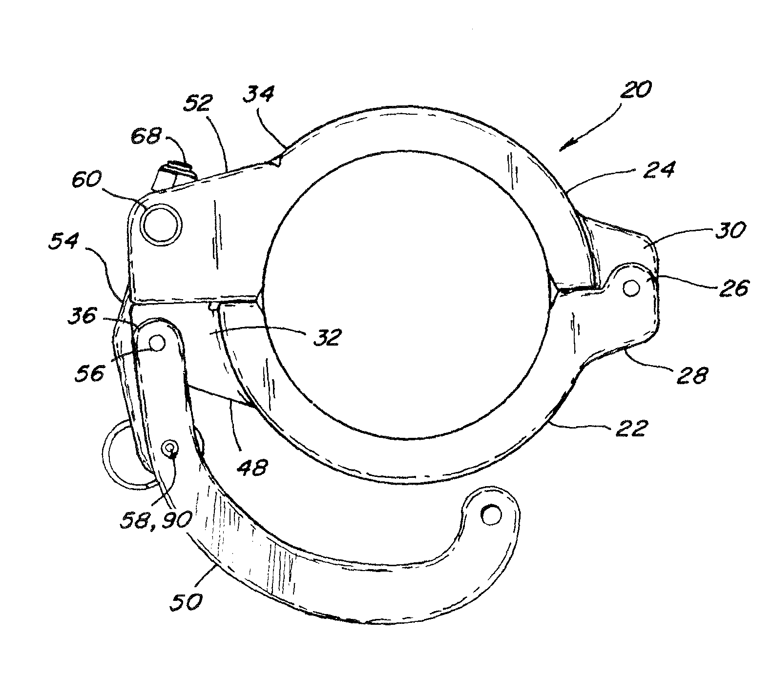
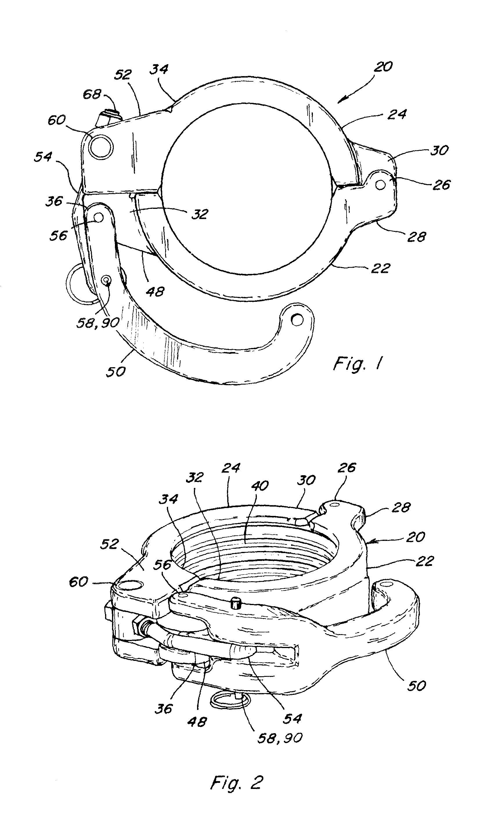
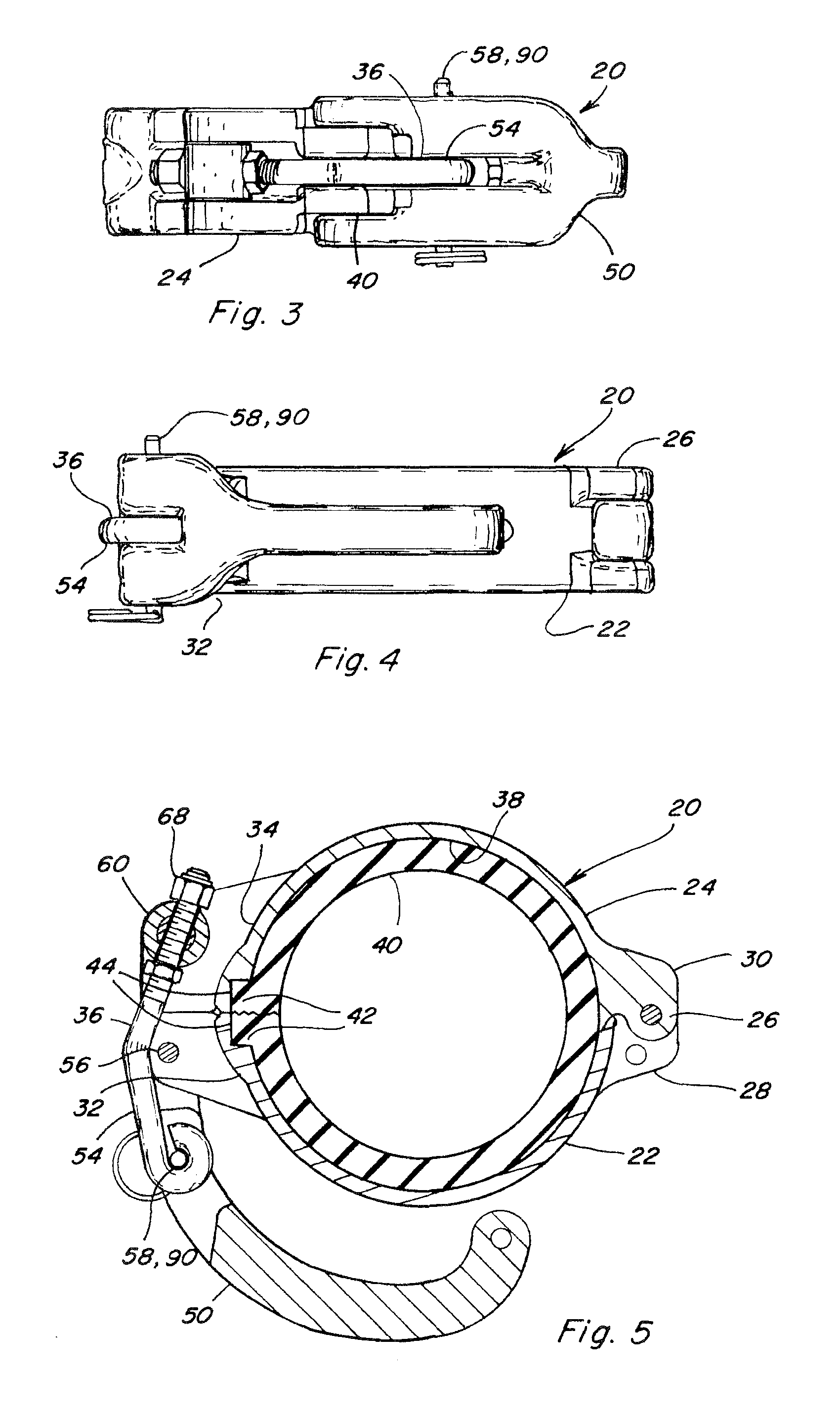
[0041]Referring to FIGS. 1 through 11A, a pipe coupler 20 constructed and operable according to the teachings of the present invention, is shown. Coupler 20 includes a first semi-circular element 22, and a second semi-circular element 24, having first end portions 28 and 30, respectively, connected for relative hinged movement by a hinge joint 26. Elements 22 and 24 include second end portions 32 and 34, which are brought together when the elements are hingedly closed, and include elements of a clamping mechanism 36 operable, including with just one hand, for securing the coupler about pipe ends, or a pipe end and a fitting, to be coupled together.
[0042]Each of semi-circular elements 22 and 24 as a generally C-shaped cross-sectional shape defining a channel 38 adapted for receiving a gasket 40, which here is a one-piece, split type gasket. Second end portions 32 and 34 of elements 22 and 24 each additionally include a cavity 42, which is open in the radial inward direction and towar...
PUM
 Abstract
Description
Claims
Application Information