Ball and socket joint

a technology socket, which is applied in the field of can solve the problems of reducing the service life of the ball and socket joint, and achieve the effect of reducing the risk of thermal overload

Inactive Publication Date: 2010-02-18
ZF FRIEDRICHSHAFEN AG
View PDF24 Cites 7 Cited by
  • Summary
  • Abstract
  • Description
  • Claims
  • Application Information

AI Technical Summary

Benefits of technology

[0006]Based on this state of the art, the basic object of the present i

Problems solved by technology

There is a risk in the prior-art ball and socket joints that the bearing shell is thermally overloa

Method used


Image

  • Ball and socket joint
  • Ball and socket joint
  • Ball and socket joint

Examples


Embodiment Construction

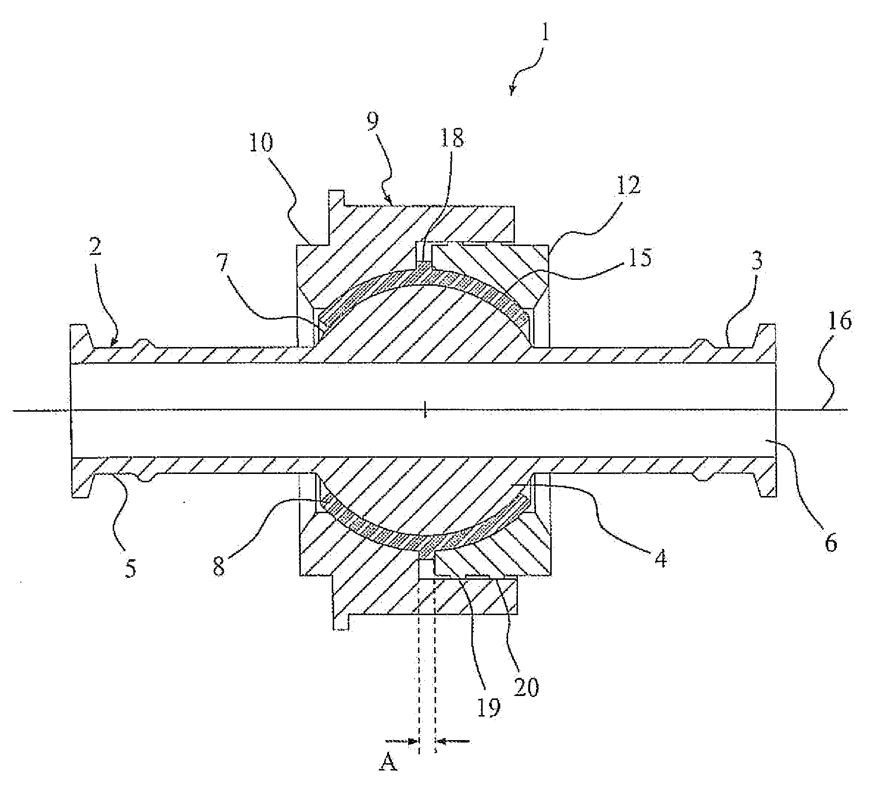
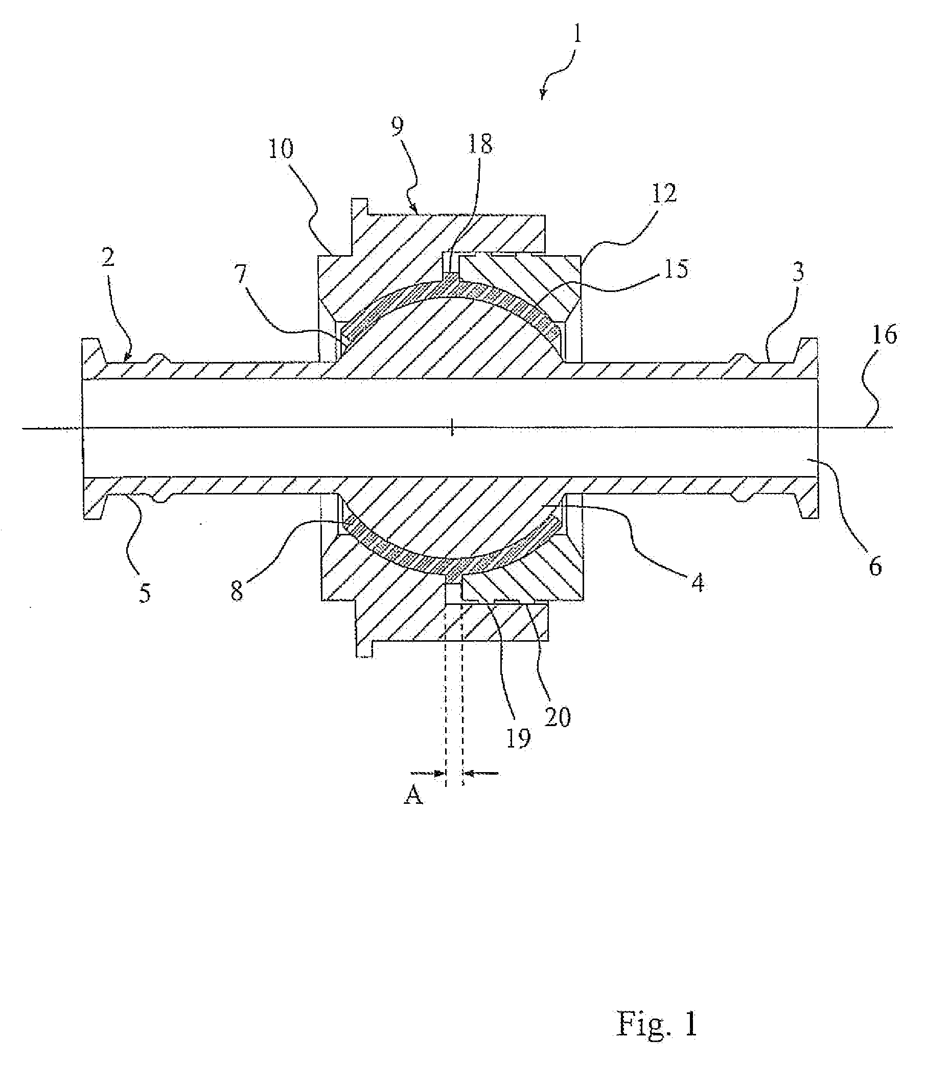
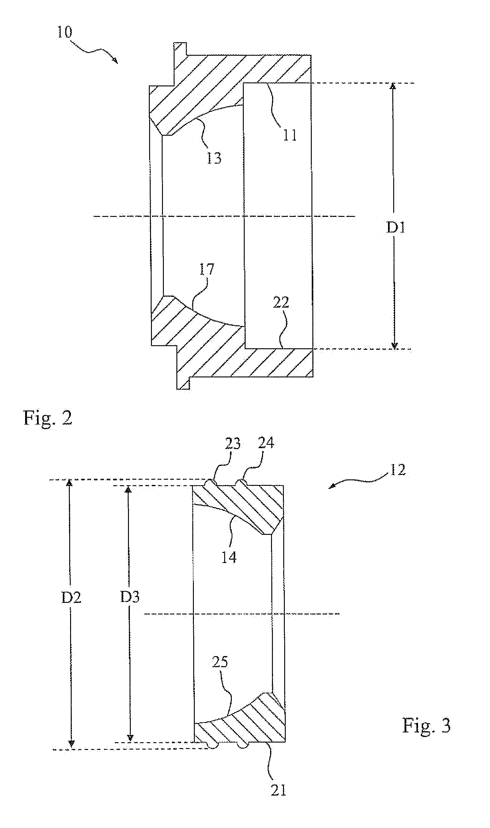
[0032]Referring to the drawings in particular, FIG. 1 shows a sectional view of an embodiment of the ball and socket joint 1 according to the present invention, which is designed as a ball sleeve joint and has a joint inner part formed as a ball sleeve 2 with a first junction area 3, with a bearing area 4, with a second junction area 5 and with a continuous recess 6. Bearing area 4 is arranged between the two essentially cylindrical junction areas 3 and 5 and is made in one piece with these. Furthermore, bearing area 4 has a partially spherical outer bearing surface 7, with which it is mounted slidingly in a bearing shell 8, which is seated in a housing 9. Housing 9 is of a two-part design and has a first housing part 10 with a cylindrical recess 11 (see FIG. 2) and a second housing part 12, which meshes with the recess 11 of the first housing part 10.

[0033]The housing parts 10 and 12 have a respective partial hollow spherical housing inner surface 13, 14 (see FIGS. 2 and 3), with w...


PUM

PropertyMeasurementUnit
Timeaaaaaaaaaa
Diameteraaaaaaaaaa
Areaaaaaaaaaaa

Abstract

A ball and socket joint is provided for a vehicle. The ball and socket joint includes a housing (9), with a joint inner part (2), which is seated in the housing (9), extends from this and is mounted movably in the housing (9) with a bearing area (4) having a spherical surface or partial spherical surface (7) via the intermediary of a bearing shell (8). The housing has two housing parts (10, 12) meshing with one another, which are firmly connected to one another by means of at least one welded connection (19, 20), wherein the two housing parts (10, 12) are braced against one another in the radial direction to form a press fit.

Description

CROSS REFERENCE TO RELATED APPLICATIONS[0001]This application is a United States National Phase application of International Application PCT / DE2007 / 001585 and claims the benefit of priority under 35 U.S.C. §119 of German Patent Application DE 10 2006 043 930.9 filed Sep. 14, 2006, the entire contents of which are incorporated herein by reference.FIELD OF THE INVENTION[0002]The present invention pertains to a ball and socket joint for a vehicle, with a housing, with a joint inner part, which is seated in the housing, extends from same and is mounted movably with a bearing area having a spherical surface or a partial spherical surface via the intermediary of a bearing shell in the housing, which has two housing parts, which mesh with one another and which are firmly connected to one another by means of at least one welded connection. The present invention pertains, furthermore, to a process for manufacturing such a ball and socket joint.BACKGROUND OF THE INVENTION[0003]Such ball and s...

Claims


Application Information

Patent Timeline
IPC IPC(8): F16C11/00B23K11/00
CPCB23K11/26F16C11/0614Y10T403/32631F16C43/02F16C11/0628B23K11/00B23P11/00F16C11/06
Inventor RECHTIEN, MARTINSCHICHTA, HOLGER
Owner ZF FRIEDRICHSHAFEN AG
Why Eureka
Try Eureka