Nostril dilator

a nasal dilator and dilator technology, applied in the field of nasal dilators, can solve the problems of lack of user modulation, limited amount of external devices, lack of constant pressure of thorner and slater patents, etc., and achieve the effect of constant pressure on the nostrils and relief from nasal congestion

Inactive Publication Date: 2010-02-18
WIEN ABRAHAM
View PDF15 Cites 13 Cited by
  • Summary
  • Abstract
  • Description
  • Claims
  • Application Information

AI Technical Summary

Benefits of technology

[0022]In one of the preferred embodiments of the invention, the tensioning element comprises an elastic strap having a pair of surface modifications (posts) for engagement with détentes and/or apertures along the length of the bow. Conversely, the medial section of the bow can include a series of posts, and the elastic strap a corresponding series of holes, for engaging the posts on the medial section of the bow. Thus, the tensioning element can be repositioned, as desired, to achieve the requisite degre...

Problems solved by technology

When such restriction is encountered, for any one of number of reasons, breathing is shifted to the mouth, which in turn can result in snoring, and possibly other conditions associated therewith (e.g. restrictive apnea).
More specifically, the external devices, of the type illustrated by the Hand patent, are limited in the amount of expansive pressure that can be exerted upon each nostril by the adhesive forces that can be applied to the external surface of the nose.
Similarly, the internal dev...

Method used


Image

  • Nostril dilator
  • Nostril dilator
  • Nostril dilator

Examples


Embodiment Construction

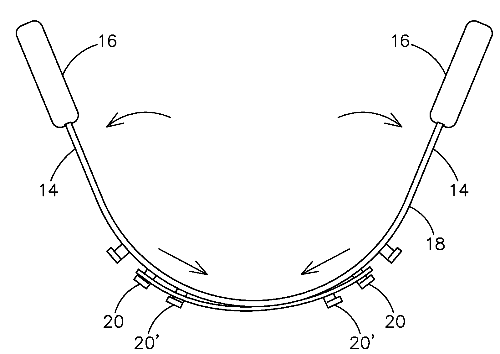
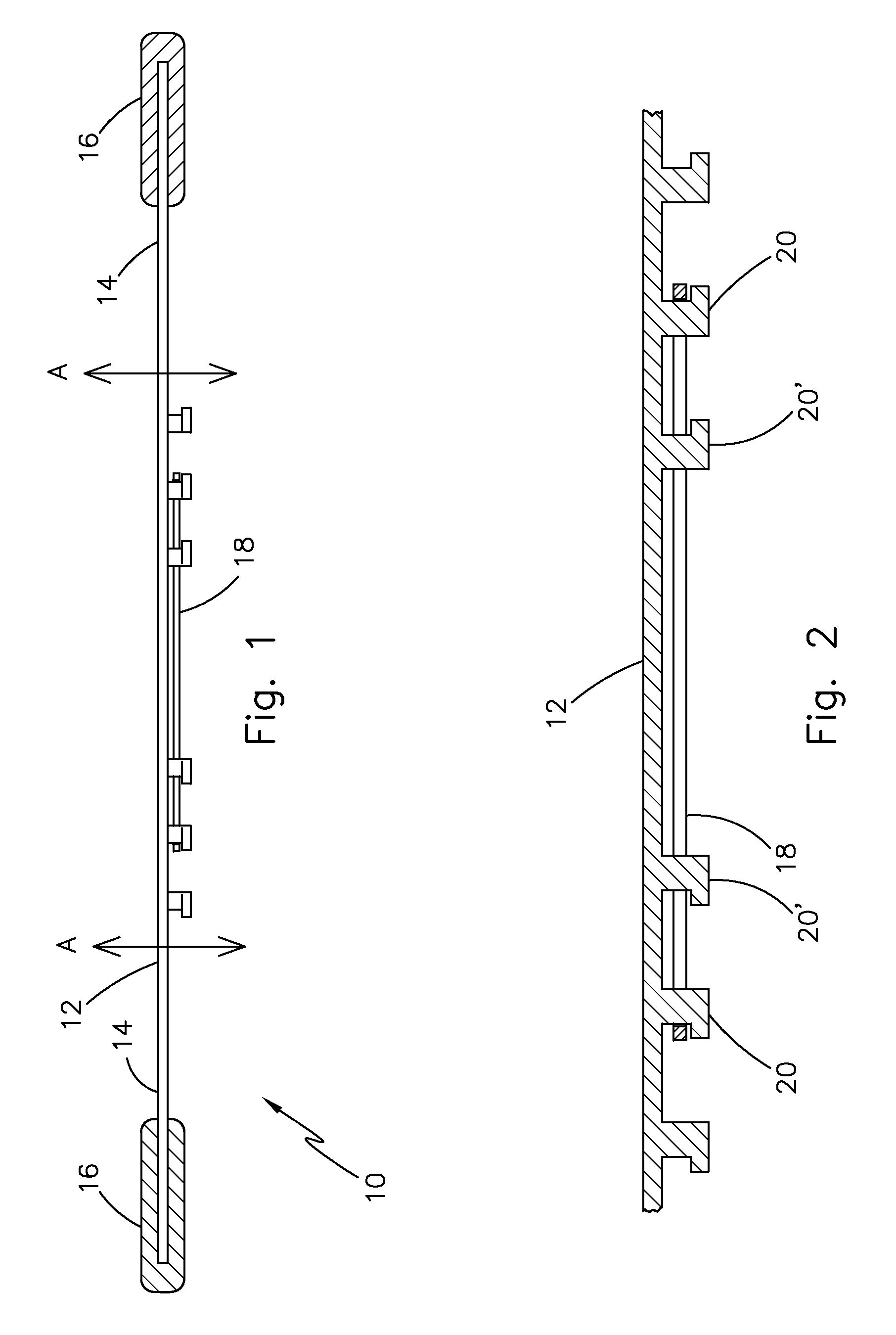
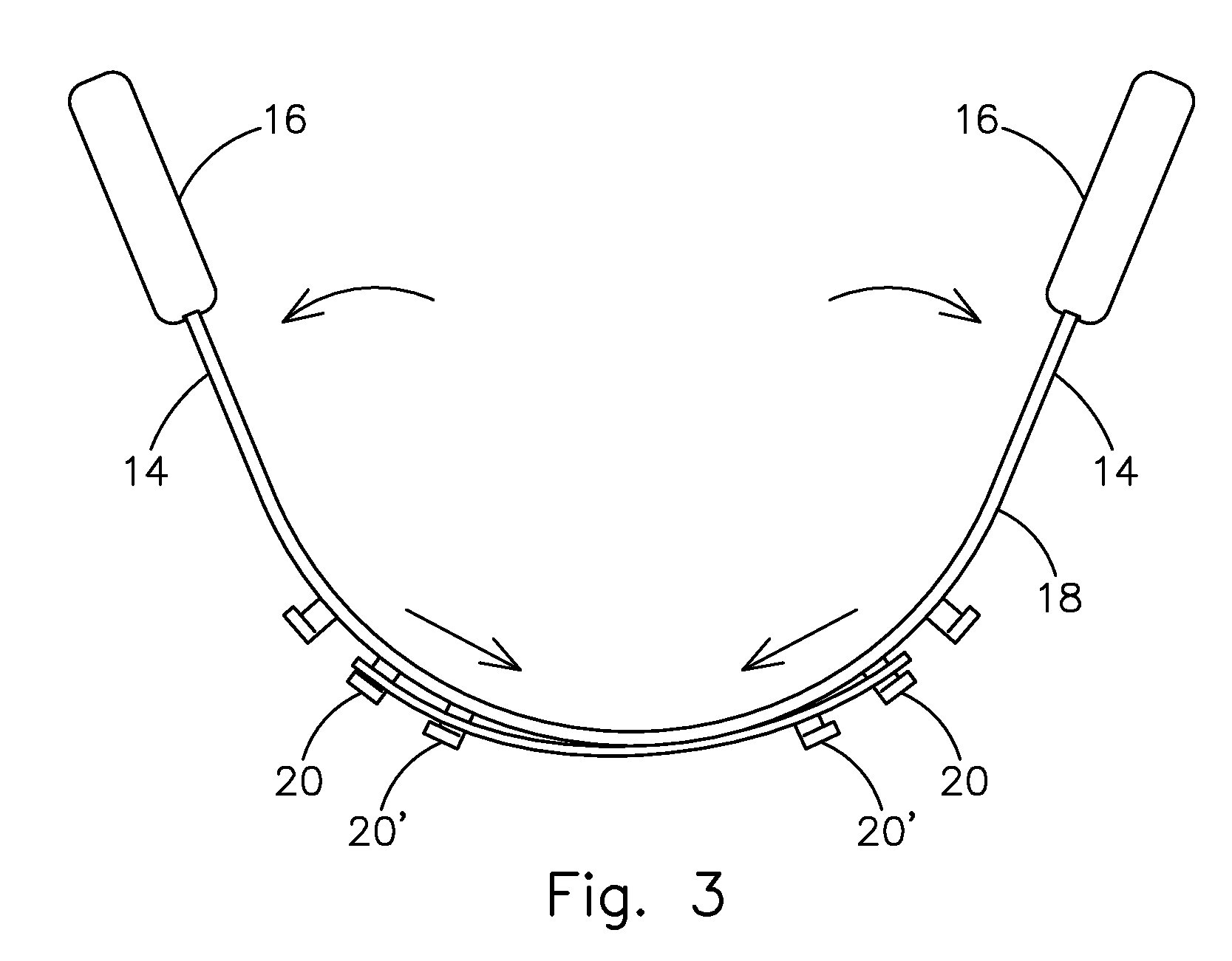
[0032]The preferred embodiment of the internal nasal prosthesis (10) of this invention is depicted in FIG. 1. The basic configuration of the prosthesis has three, and preferable four, basic elements:[0033]a resilient flexible bow (12) which preferably comprises a planar strip of plastic material capable of bending and taking the shape of a “V” or “U”.[0034]an appendage (14) on each end of the bow, preferably comprising a tubular member, of an internal diameter sufficient to be fitted on each end of the bow;[0035]a pair of pads (16), or cushioning elements, on the free end of each of the appendages, for engagement of the surface of the internal nasal passages of an individual; and,[0036]a tensioning element or spreader (18, 18′), for engagement with one of more surface features, (e.g. détentes, holes and / or posts), so as to provide for incremental positioning (20, 20″) the tensioning element relative to the surface of the resilient flexible bow (12).

[0037]In practice, the bow (12) ...


PUM


Abstract

A device for relieving congestion in restricted nasal passages, by the dilation thereof with an internal prosthesis placed within the nasal passages of an individual. This prosthesis comprises an adjustable bow having a pair of appendages extending from each end thereof. A separate tensioning element engages complimentary features on/in the bow to limit flexure thereof, and thereby provide a counterforce to bending of the bow. Accordingly, when the bow is flexed or bent, the extent of flex or bending of the bow is constrained by the tensioning element. The combined effect of the natural recoil of the resilient bow from the distended to flat position, combined with the counter forces imparted to the bow by the tensioning element, causes each appendage on the end of the bow to exert a constant pressure within each nasal passage to maintain such passages in a relatively open position.

Description

BACKGROUND OF THE INVENTION[0001]1. Field of the Invention[0002]This invention relates to a device. More specifically, this invention is directed to a device for relieving congestion in restricted nasal passages, by the dilation thereof with an internal prosthesis placed within the nasal passages of an individual. This prosthesis is adjustable, and under tension, so as to thereby exert constant pressure within each nasal passage to maintain such passages in a relatively dilated / open position.[0003]2. Description of the Prior Art[0004]The natural tendency is for human beings to breath through their nose, unless otherwise restricted from doing so. When such restriction is encountered, for any one of number of reasons, breathing is shifted to the mouth, which in turn can result in snoring, and possibly other conditions associated therewith (e.g. restrictive apnea).[0005]Over the years a number of devices have been developed to lessen the nasal restriction and improve nasal breathing pa...

Claims


Application Information

Patent Timeline
IPC IPC(8): A61M29/00
CPCA61F5/08
Inventor WIEN, ABRAHAM
Owner WIEN ABRAHAM
Why Eureka
Try Eureka