Programmable reverse thrust detent system and method

a reverse thrust detent and programmable technology, applied in process and machine control, instruments, navigation instruments, etc., can solve problems such as insufficient landing performance resolution or non-optimum performance, autobrake system, uneven deceleration,

Inactive Publication Date: 2010-02-18
THE BOEING CO
View PDF28 Cites 29 Cited by
  • Summary
  • Abstract
  • Description
  • Claims
  • Application Information

AI Technical Summary

Benefits of technology

[0006]The disclosure is further generally directed to a reverse thrust detent method for an aircraft having at least one aircraft engine. An illustrative embodiment of the reverse thrust detent method includes providing a throttle quadrant for the aircraft, providing programmable and adjustable intermediate reverse thrust detent position on the throttle quadrant, defining a range of possible engine reverse thrust detent settings when using an intermediate level of reverse thrust detent position, selecting an optimum engine reverse thrust setting corresponding to that needed to precisely decelerate a position abeam an intended landing runway taxiway exit, setting the throttle quadrant to an optimum intermediate reverse thrust detent position for each intended use and operating the at least one aircraft engine according to the optimum engine reverse thrust setting for that landing, which aids the aircraft to decelerate to a safe taxi speed at a position abeam the intended landing runway taxiway exit.

Problems solved by technology

Thus, if a pilot wishes to stop the airplane at a certain point on the runway, for example at a runway exit, it may be unlikely that the AUTOBRAKE system would provide a deceleration setting that matches the stopping distance to the selected runway stop point.
Both of the above conditions may result in uneven deceleration that may be apparent to the airplane passengers.
In some applications, however, use of only the MAX Reverse setting or the IDLE Reverse setting may provide insufficient landing performance resolution or non-optimum performance.

Method used


Image

  • Programmable reverse thrust detent system and method
  • Programmable reverse thrust detent system and method
  • Programmable reverse thrust detent system and method

Examples


Embodiment Construction

[0015]The following detailed description is merely exemplary in nature and is not intended to limit the described embodiments or the application and uses of the described embodiments. As used herein, the word “exemplary” or “illustrative” means “serving as an example, instance, or illustration.” Any implementation described herein as “exemplary” or “illustrative” is not necessarily to be construed as preferred or advantageous over other implementations. All of the implementations described below are exemplary implementations provided to enable persons skilled in the art to make or use the invention and are not intended to limit the scope of the invention which is defined by the claims. Furthermore, there is no intention to be bound by any expressed or implied theory presented in the preceding technical field, background, brief summary or the following detailed description.

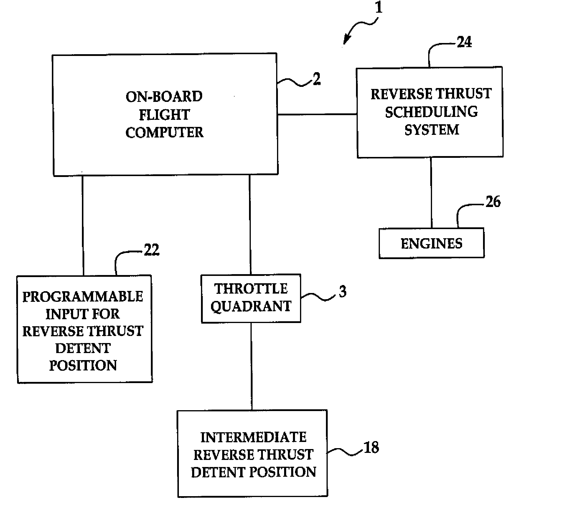
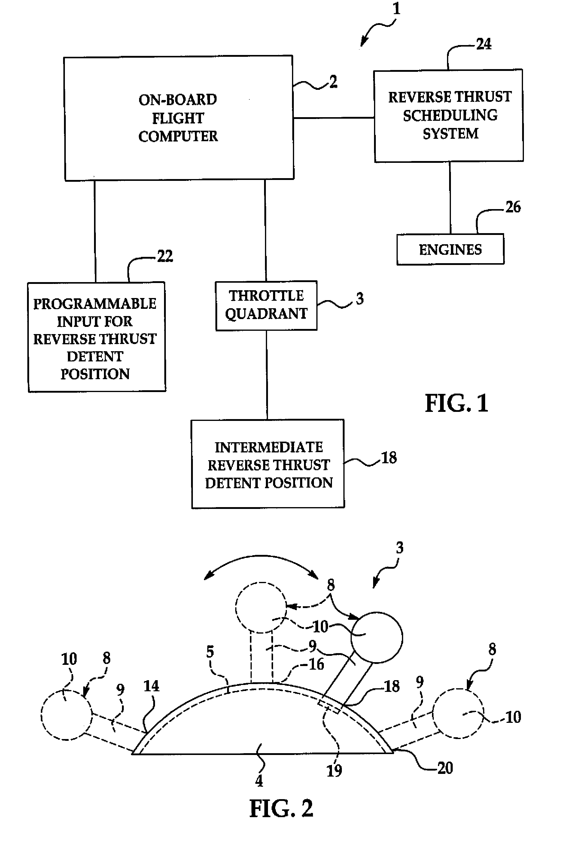
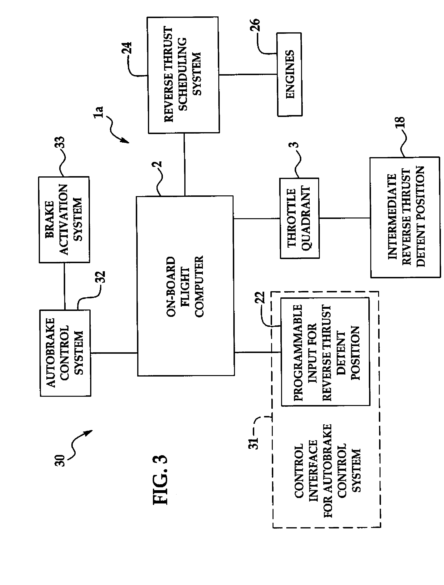
[0016]The present disclosure is generally directed to a programmable reverse thrust detent system for an aircraf...


PUM


Abstract

A reverse thrust detent system for an aircraft includes a throttle quadrant having an intermediate reverse thrust detent position, a reverse thrust scheduling system interfacing with the throttle quadrant, at least one aircraft engine interfacing with the reverse thrust scheduling system and a programmable input interfacing with the reverse thrust scheduling system and adapted to receive an engine reverse thrust setting. The reverse thrust scheduling system is adapted to operate the at least one aircraft engine according to the engine reverse thrust setting responsive to actuation of the intermediate reverse thrust detent position of the throttle quadrant. A reverse thrust detent method for an aircraft is also disclosed.

Description

CROSS-REFERENCES TO RELATED APPLICATIONS[0001]This application is related to and hereby incorporates by reference in its entirety application Ser. No. 11 / 777,351, entitled “System and Method for Optimized Runway Exiting”.TECHNICAL FIELD OF THE INVENTION[0002]The disclosure generally relates to aircraft braking techniques. More particularly, the disclosure relates to a programmable reverse thrust detent system and method for the optimization of landing runway deceleration and exiting of an aircraft.BACKGROUND OF THE INVENTION[0003]Conventional aircraft AUTOBRAKE systems may control airplane deceleration to one of several predetermined aircraft deceleration settings. Thus, if a pilot wishes to stop the airplane at a certain point on the runway, for example at a runway exit, it may be unlikely that the AUTOBRAKE system would provide a deceleration setting that matches the stopping distance to the selected runway stop point. The pilot's choice may be to select one of the deceleration se...

Claims


Application Information

Patent Timeline
Patent Type & Authority Applications(United States)
IPC IPC(8): G06F19/00B64C13/14
CPCB64D31/04G05D1/0083F02K1/76B64D31/00B64D31/02B64D31/06B64D31/14B64D45/04G05D1/00G05D13/00
Inventor GOODMAN, WILLIAM L.IMRICH, THOMAS
Owner THE BOEING CO
Why Eureka
Try Eureka