

Exhaust heat recovery system
a heat recovery system and exhaust heat technology, applied in the direction of combustion-air/fuel-air treatment, lighting and heating apparatus, separation processes, etc., can solve the problem of engine cooling water being overheated, and achieve the effect of restricting the overheating of the coolan
- Summary
- Abstract
- Description
- Claims
- Application Information
AI Technical Summary
Benefits of technology
Problems solved by technology
Method used
Image

Examples
first embodiment
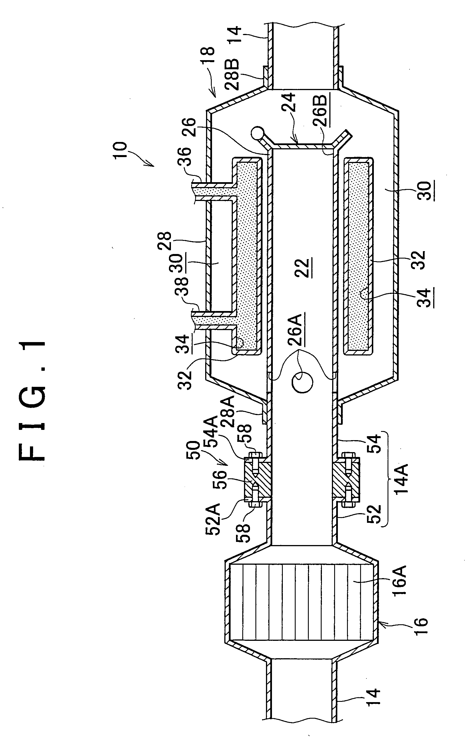
[0036]An exhaust heat recovery system 10 according to the invention will be described with reference to FIGS. 1 and 2. In the following description, the terms “upstream” and “downstream” of exhaust passage indicate upstream and downstream in the flowing direction of exhaust gas.
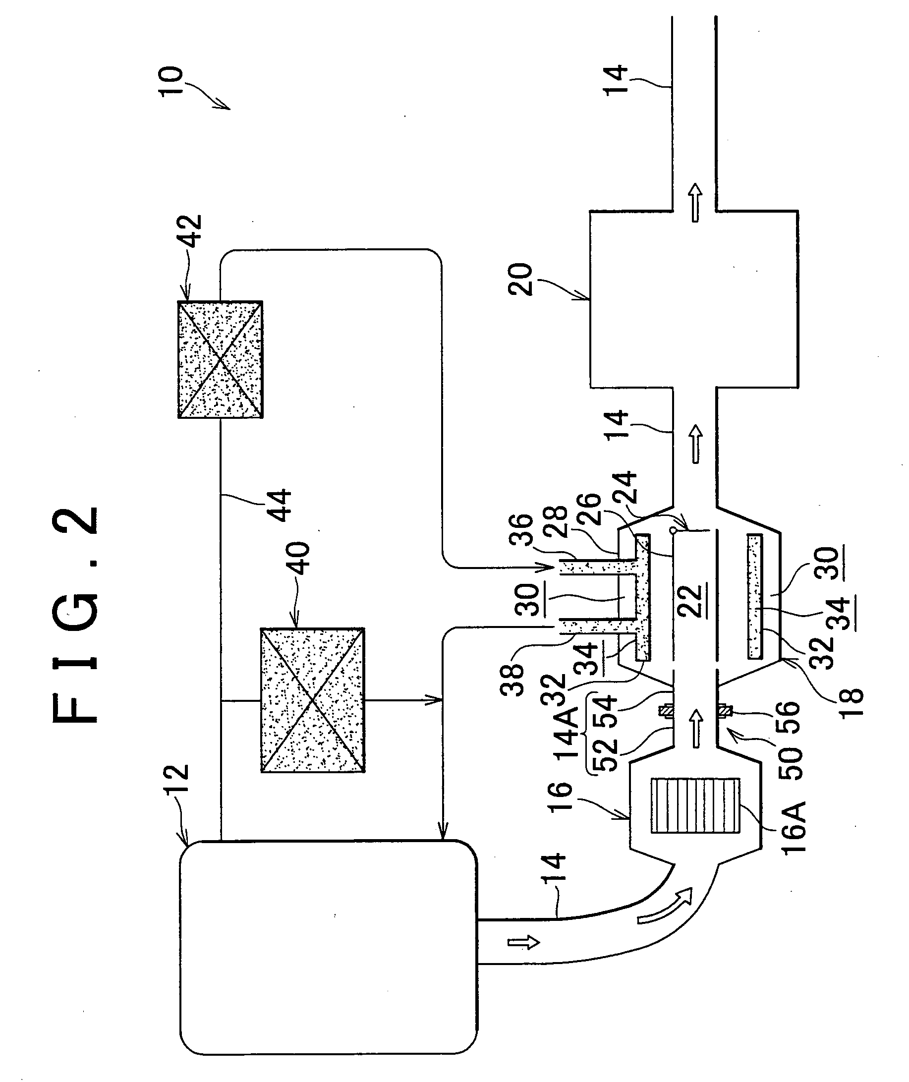
[0037]In FIG. 2, the exhaust heat recovery system 10 is entirely shown in a schematic flow diagram. As shown in this diagram, the exhaust heat recovery system 10 recovers heat of exhaust gas in an engine (i.e., an internal combustion engine) 12 of a motor vehicle through heat exchange with engine cooling water, and uses the recovered heat for air heating in the cabin or the like, or boosting the warm-up of the engine 12.
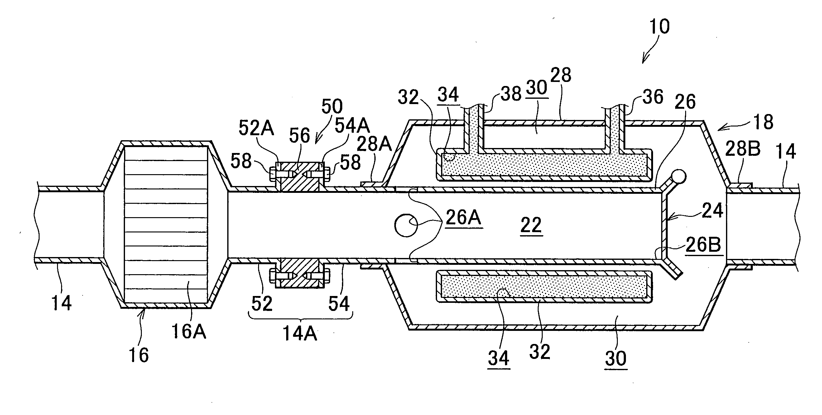
[0038]An exhaust gas pipe 14 that forms an exhaust passage is connected to the engine 12, and leads exhaust gas out. A catalytic converter 16, an exhaust heat exchanger 18 and a main muffler 20 are disposed in that order from the upstream side of exhaust passage formed by the exhaust gas pipe ...
second embodiment
[0067]In the exhaust heat recovery system 60 the transferred heat from the catalytic converter 16 to the exhaust gas pipe 66 is radiated to the outside air by the heat radiating fins 62. Therefore, in the exhaust heat recovery system 60, the released heat from the catalytic converter 16 is restrained from reaching the exhaust heat exchanger 18. In particular, in the exhaust heat recovery system 60, the catalytic converter 16 and the exhaust heat exchanger 18 are communicated via the exhaust gas pipe 66, and exhaust gas pipe the heat transfer restriction means 63 is provided on the exhaust gas pipe 66. Thus, the released heat from the catalytic converter 16 is reliably restrained from reaching the exhaust heat exchanger 18 because the catalytic converter 16 is spaced from the exhaust heat exchanger 18 via the exhaust gas pipe 66 while the heat transfer restriction means 64 is further provided on a heat transfer passage (i.e., the exhaust gas pipe 66).
[0068]In this manner, according ...
fifth embodiment
[0080]Incidentally, in the foregoing fifth embodiment, the heat transfer restriction means 94 includes the heat insulator 56. However, the invention is not limited to this construction. Alternatively, the heat insulator 56 may not be provided.
[0081]FIG. 8 shows portions of an exhaust heat recovery system 100 according to a sixth embodiment of the invention. As shown in FIG. 8, the exhaust heat recovery system 100 is different from the systems of the first to fifth embodiments in that the catalytic converter 16 and the exhaust heat exchanger 18 are communicated without via the exhaust gas pipe 14A.
[0082]Concretely, a conical portion 104 that covers a portion of a downstream side of a catalyst case 102 in the catalytic converter 16 is provided integrally with an upstream end 26C of an inner pipe 26 in the exhaust heat recovery system 100. An upstream end 28A of an outer pipe 28 is butted on the side of the upstream end 26C of the inner pipe 26.
[0083]Furthermore, communication holes 26...
PUM
| Property | Measurement | Unit |
|---|---|---|
| ambient temperature | aaaaa | aaaaa |
| temperature | aaaaa | aaaaa |
| heat-insulating | aaaaa | aaaaa |
Abstract
Description
Claims
Application Information