Radiation efficiency measuring apparatus and radiation efficiency measuring method

Inactive Publication Date: 2010-02-25
MURATA MFG CO LTD
View PDF8 Cites 17 Cited by
  • Summary
  • Abstract
  • Description
  • Claims
  • Application Information

AI Technical Summary

Benefits of technology

[0013]The present invention has been developed in view of the above-described problems, and it is an object of the present invention to provide a

Problems solved by technology

However, Japanese Unexamined Patent Application Publication No. 2000-214201 does not disclose a specific calculation method of the radiation efficiency.
In addition, the measuring apparatus disclosed in Japanese Unexamined Patent Application Publication No. 2000-214201 can result in a measurement error of about 3 dB, which is an undesirably low measurement accuracy.
For this reason, the measuring system disclosed in Japanese Unexamined Patent Application Publication No. 2000-338155 requires a long period of time for measurement.
Moreover, a moving mechanism for moving the measuring antenna across the whole solid angle becomes bulky.
Furthermore, t

Method used


Image

  • Radiation efficiency measuring apparatus and radiation efficiency measuring method
  • Radiation efficiency measuring apparatus and radiation efficiency measuring method
  • Radiation efficiency measuring apparatus and radiation efficiency measuring method

Examples


Embodiment Construction

[0030]A radiation efficiency measuring apparatus of an embodiment of the present invention is described below with reference to the accompanying drawings.

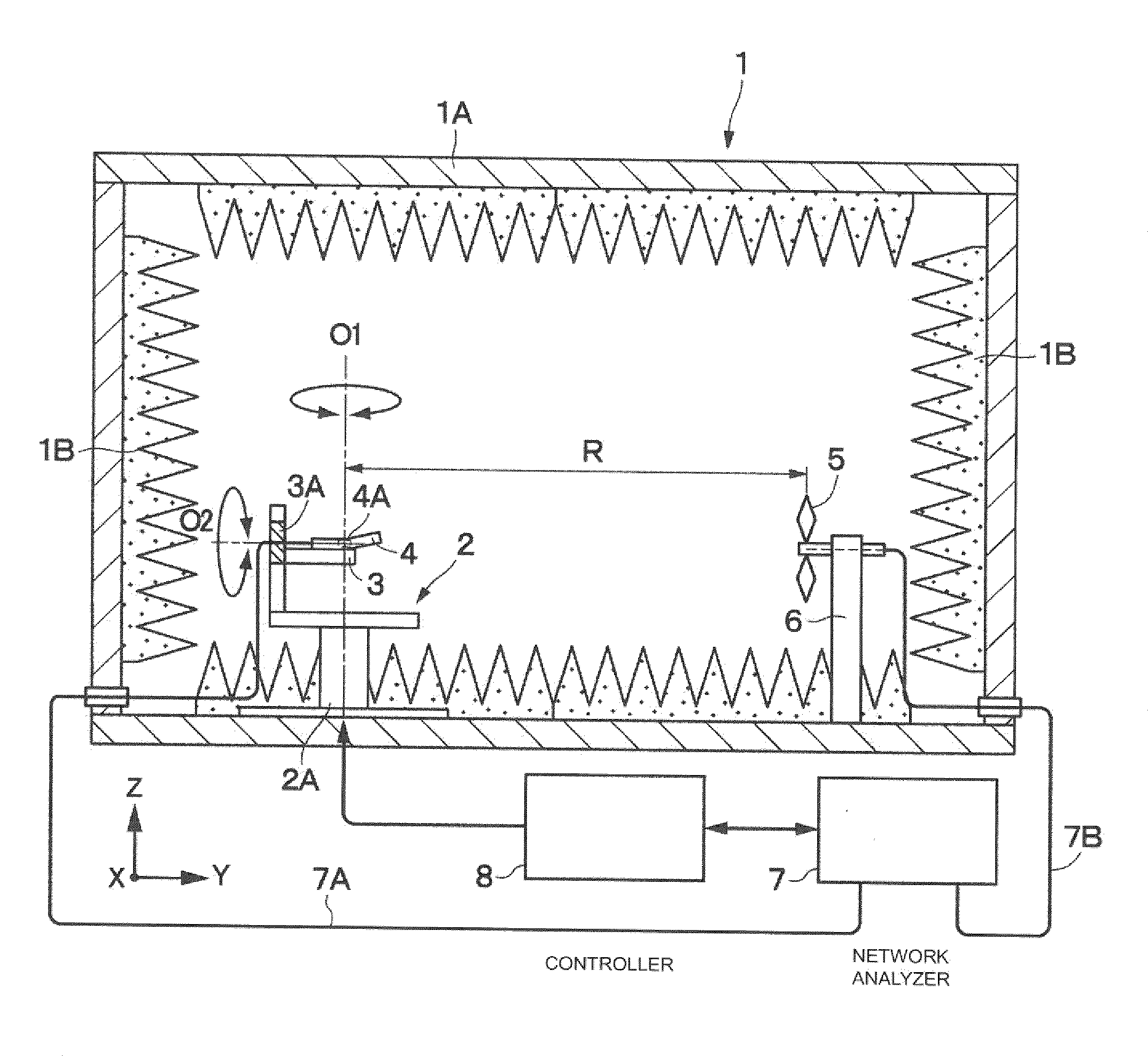
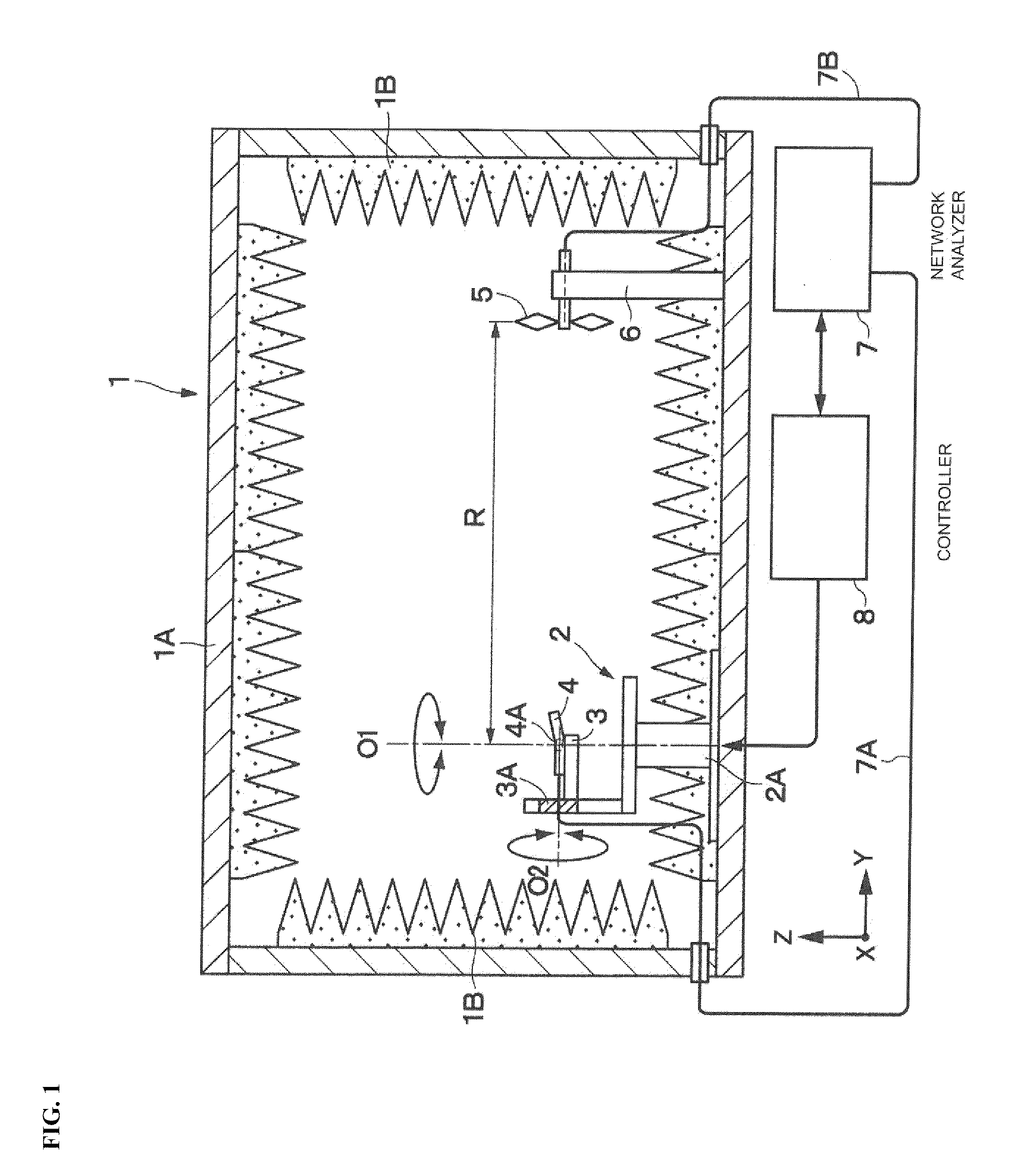
[0031]Referring to FIG. 1, an anechoic chamber 1 includes a chamber 1A made of aluminum plates having a thickness of 1-2 mm and a radiowave absorber 1B arranged within the chamber 1A. The size dimensions of the anechoic chamber 1 range are within about 50-100 cm in a width direction (X direction), a length direction (Y direction), and a height direction (Z direction). The anechoic chamber 1 blocks electromagnetic waves from the outside while preventing internal electromagnetic waves from reflecting therewithin.

[0032]An azimuth table 2 constitutes the azimuth angle rotation means and is arranged close to the left inner wall surface of the anechoic chamber 1, for example. The azimuth table 2 includes a rotation driver 2A such as a drive motor, and rotates driven by the rotation driver 2A to an azimuth angle θ around an O1 axis in par...


PUM


Abstract

A target antenna 4A to be measured and a measuring antenna 5 are placed within an anechoic chamber 1. A first azimuth angle plane radiation pattern S21 (R,θ,φ) is measured using a network analyzer 7 with an elevation angle φ of the target antenna 4A fixed to a first angle φ1. Next, a second azimuth angle plane radiation pattern S21 (R,θ,φ) is measured using the network analyzer 7 with the elevation angle φ of the target antenna 4A fixed to a second angle φ2 different from the first angle φ1 by 90 degrees. A radiation efficiency of the target antenna 4A is measured by integrating in a spherical shape the azimuth angle plane radiation patterns S21 (R,θ,φ) at two planes.

Description

CROSS REFERENCE TO RELATED APPLICATIONS[0001]The present application is a continuation of International Application No. PCT / JP2008 / 057575, filed Apr. 18, 2008, which claims priority to Japanese Patent Application No. 2007-122448 filed May 7, 2007, the entire contents of each of these applications being incorporated herein by reference in their entirety.BACKGROUND OF THE INVENTION[0002]1. Field of the Invention[0003]The present invention relates to a radiation efficiency measuring apparatus and a radiation efficiency measuring method for measuring a radiation efficiency of an antenna for use in a cellular phone or the like.[0004]2. Description of the Related Art[0005]An apparatus for measuring a radiation efficiency or the like of an antenna used in a cellular phone or the like is known and generally discussed in, for example, Japanese Unexamined Patent Application Publication (Translation of PCT Application) No. 2000-214201, Japanese Unexamined Patent Application Publication (Transl...

Claims


Application Information

Patent Timeline
IPC IPC(8): G01R29/10
CPCG01R29/105G01R29/0821G01R29/10G01R29/08
Inventor KITADA, HIROSHI
Owner MURATA MFG CO LTD
Why Eureka
Try Eureka