Image display apparatus and image display method

a technology of image display and display apparatus, which is applied in the direction of electrical apparatus, color television details, instruments, etc., can solve the problems of short illumination time of light source, apparatus needs a complicated configuration, and display image becomes darker, so as to shorten the receiving time of image signal, shorten the writing time of display panel, and prolong the illumination time of display panel

Inactive Publication Date: 2010-02-25
MITSUBISHI ELECTRIC CORP
View PDF4 Cites 33 Cited by
  • Summary
  • Abstract
  • Description
  • Claims
  • Application Information

AI Technical Summary

Benefits of technology

[0010]In the present invention, since an image-for-left-eye signal of the reduced number of lines and an image-for-right-eye signal of the reduced number of lines are transmitted to the display unit, the receiving time for the image signal can be shortened. Further, in the present invention, since the display unit duplicates an image signal of each line of the image-for-left-eye signal of the reduced number of lines and the image-for-right-eye signal of the reduced number of lines supplied from the display controller to produce the same plural image signals for plural lines and simultaneously writes the produced plural image signals for plural lines in the display panel to display an image, the writing time in the display panel can be shortened. For these reasons, the present invention can have an advantageous effect that the illuminator can illuminate the display panel for longer time as long as crosstalk between an image for left eye and an image for right eye can be avoided, an bright image can be displayed on the display panel and crosstalk between an image for left eye and an image for right eye can be avoided. Furthermore, since there is no need to provide plural light sources corresponding to plural lines respectively, the present invention has an advantageous effect that the apparatus does not need to have a complicate configuration.

Problems solved by technology

However, this method has a problem of crosstalk, by which part of an image for left eye is viewed undesirably by a right eye and / or part of an image for right eye is viewed undesirably by a left eye.
However, in the image display method disclosed in Patent Document 1, the illuminating time of the light source becomes short, and therefore there is a problem that the displayed image becomes darker than that when the light source continuously illuminates the display panel.
However, in this case, there is another problem that the apparatus needs a complicated configuration.

Method used


Image

  • Image display apparatus and image display method
  • Image display apparatus and image display method
  • Image display apparatus and image display method

Examples


first embodiment

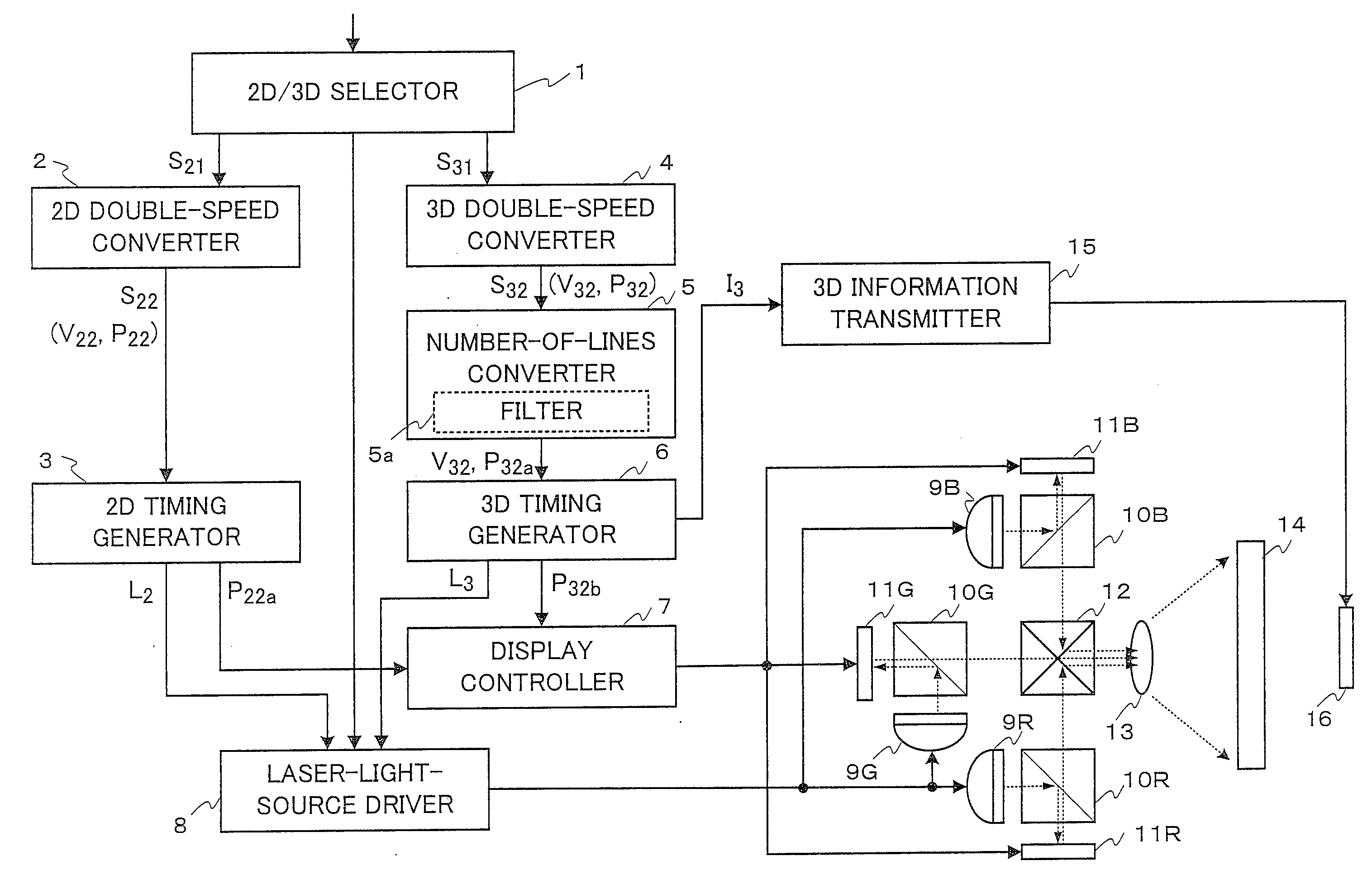
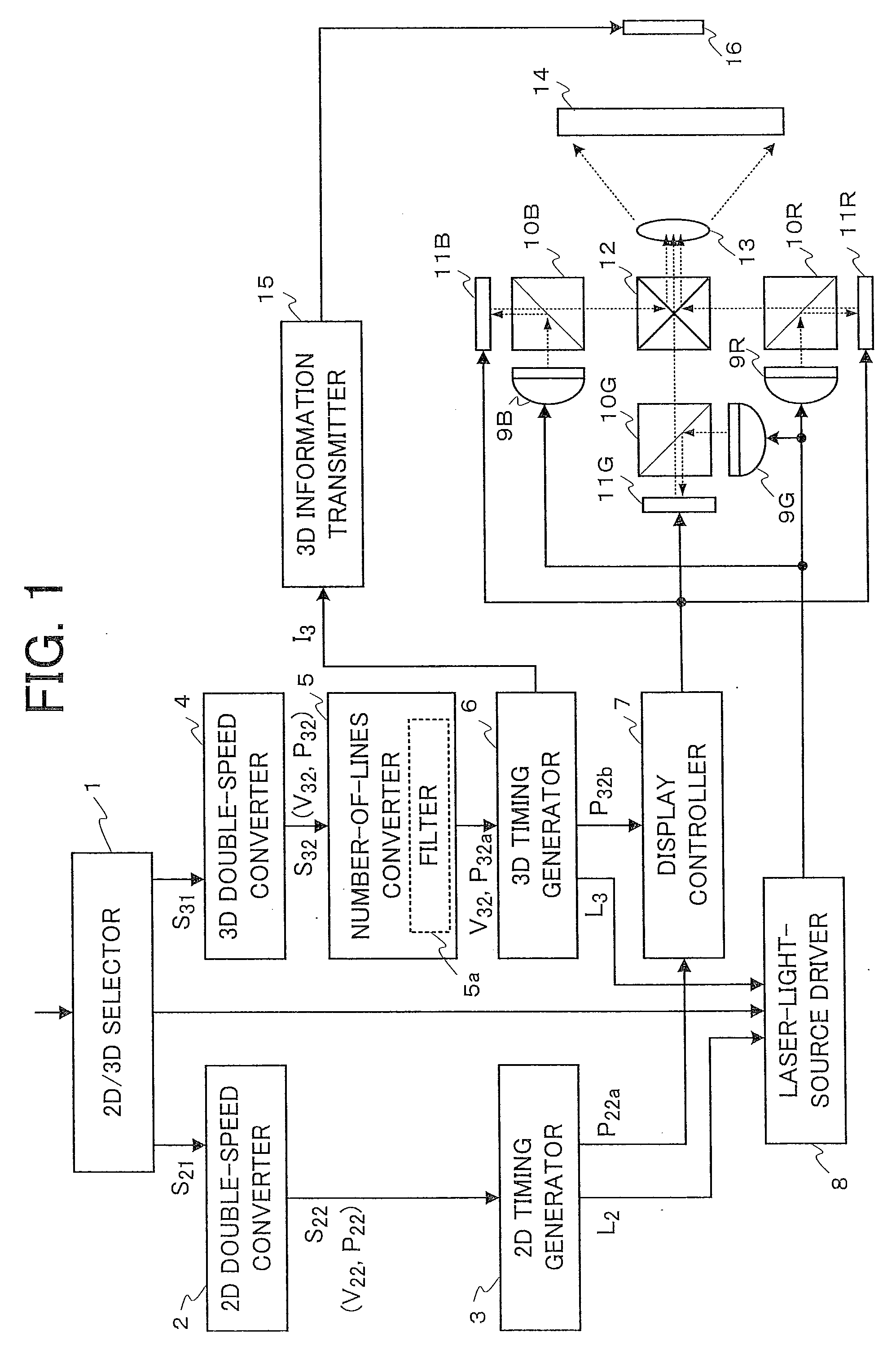
[0025]FIG. 1 is a block diagram schematically showing a configuration of an image display apparatus according to the first embodiment (i.e., an apparatus for performing an image display method according to the first embodiment) of the present invention. As shown in FIG. 1, the image display apparatus according to the first embodiment includes a two-dimensional image / a stereoscopic image (2D / 3D) selector 1, a two-dimensional image (2D) double-speed converter 2, and a two-dimensional image (2D) timing generator 3. Further, the image display apparatus according to the first embodiment includes a stereoscopic image (3D) double-speed converter 4, a number-of-lines converter 5, a stereoscopic image (3D) timing generator 6, and a stereoscopic image (3D) information transmitter 15. Furthermore, the image display apparatus according to the first embodiment includes a display controller 7 and a laser-light-source driver 8.

[0026]Further, as shown in FIG. 1, the image display apparatus accordin...

second embodiment

[0044]FIGS. 8A and 8B are explanatory diagrams showing a case where a stereoscopic image signal is an interlace signal in an image display apparatus according to the second embodiment (i.e., an apparatus for performing an image display method according to the second embodiment) of the present invention. Although the first embodiment describes a case where the input image signal is a non-interlace signal, the present invention can be applied to a case where the input image signal is an interlace signal. The second embodiment is the same as the first embodiment except for a point that the input image signal in the first embodiment is a non-interlace signal. Therefore, a description of the second embodiment will be made also with reference to FIG. 1.

[0045]A description will be made as to only an image for left eye of an interlace signal that has been converted to 120 Hz by the 3D double-speed converter 4. Regarding only an image for left eye in a 3D double-speed image signal of a frequ...

third embodiment

[0048]FIGS. 9A and 9B are explanatory diagrams showing a case where a stereoscopic image signal is an interlace signal in an image display apparatus according to the third embodiment (i.e., an apparatus for performing an image display method according to the third embodiment) of the present invention. In the third embodiment, a measure for reducing the line flicker is provided in addition to the constitutional elements of the second embodiment. Except for this point, the third embodiment is substantially the same as the above-described second embodiment.

[0049]In the above-described second embodiment, as shown as pattern A2 in FIG. 8B, when a line, on which the image data changes from a black picture element shown by a shaded dot to a white picture element shown by a white dot, is the 3rd line in a top field and the 2nd line in a bottom field, the line flicker may be noticeable occasionally. This is because as shown as numeral 40 in FIG. 8B, when a line (ST13) to be displayed is dupl...


PUM


Abstract

An image display apparatus including a display unit having a display panel; an illuminator; a number-of-lines converter for changing each of number of lines in one frame of an image-for-left-eye signal and number of lines in one frame of an image-for-right-eye signal to a reduced number of lines; a timing generator for generating a display timing signal and an illuminating timing signal; a display controller; and an illuminator driver for causing the illuminator to apply light to the display panel at timing synchronized with the display timing signal every one frame; wherein the display unit duplicates an image signal of each line of the image-for-left-eye signal of the reduced number of lines and the image-for-right-eye signal of the reduced number of lines to produce the same plural image signals for plural lines and simultaneously writes the produced signals for plural lines in the display panel to display an image.

Description

BACKGROUND OF THE INVENTION[0001]1. Field of the Invention[0002]The present invention relates to an image display apparatus and an image display method for alternately displaying an image for left eye and an image for right eye in a time-division manner to display a stereoscopic image.[0003]2. Description of the Related Art[0004]A method of displaying a stereoscopic image by making an image for left eye and an image for right eye impinge on a left eye and a right eye respectively has been put to practical use. However, this method has a problem of crosstalk, by which part of an image for left eye is viewed undesirably by a right eye and / or part of an image for right eye is viewed undesirably by a left eye. In order to resolve this problem, there is proposed an image display method of reducing crosstalk between an image for left eye and an image for right eye by controlling light illumination timing of a light source for illuminating a display panel so that the light source is in an ...

Claims


Application Information

Patent Timeline
Patent Type & Authority Applications(United States)
IPC IPC(8): H04N13/04
CPCG09G3/3406G09G3/3611H04N13/0029H04N13/0454H04N13/0051H04N13/0434H04N13/0438H04N13/0048H04N13/337H04N13/341H04N13/167H04N13/161H04N13/359H04N13/139
Inventor OKAZAKI, KOUJINAGASE, AKIHIROYAMAMURO, TAKAHIKOKAGAWA, SHUICHISUGIURA, HIROAKI
Owner MITSUBISHI ELECTRIC CORP
Why Eureka
Try Eureka