Delay mechanism for automatic injection device

Active Publication Date: 2010-02-25
ELI LILLY & CO
View PDF38 Cites 184 Cited by
  • Summary
  • Abstract
  • Description
  • Claims
  • Application Information

AI Technical Summary

Benefits of technology

[0007]One advantage of the present invention is that a delay mechanism may be provided which can be adapted for use with differently configured automatic injection devices.
[0008]Another advantage of the present invention is that a delay mechanism may be provided for an automatic injection device which is not substantially involved with operational forces applied to the syringe during needle insertion and then injection.
[0009]Another advantage of the present invention is that a delay mechanism may be provided for an automatic injection device which allows a timely retraction of the needle without a releasing of the drive actuator from the syringe.
[001

Problems solved by technology

One difficulty with designing an automatic injector with a needle retracting feature is ensuring both that the full desired contents of the syringe have been injected and that the syringe needle is properly retr

Method used


Image

  • Delay mechanism for automatic injection device
  • Delay mechanism for automatic injection device
  • Delay mechanism for automatic injection device

Examples


Embodiment Construction

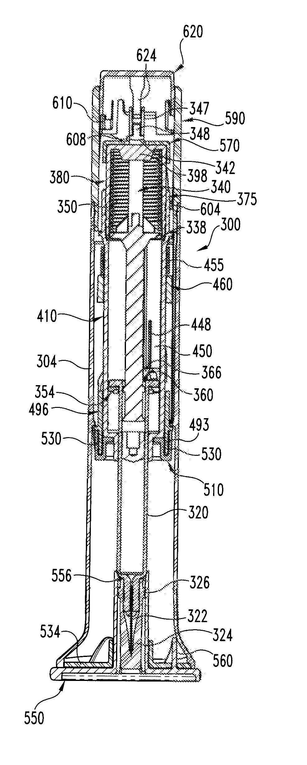
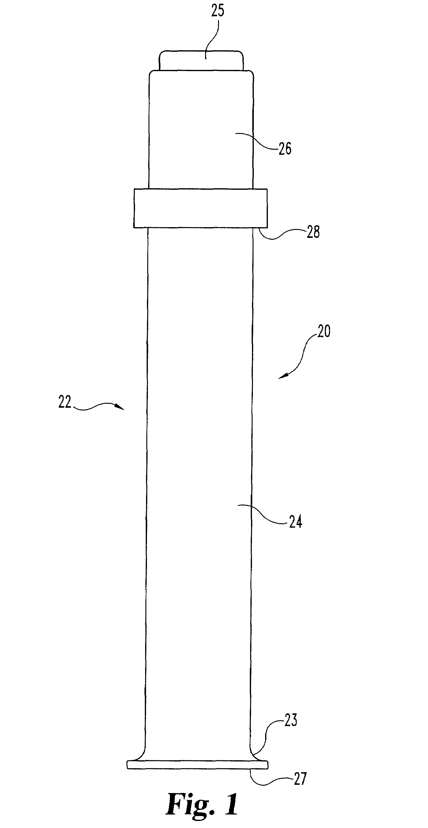
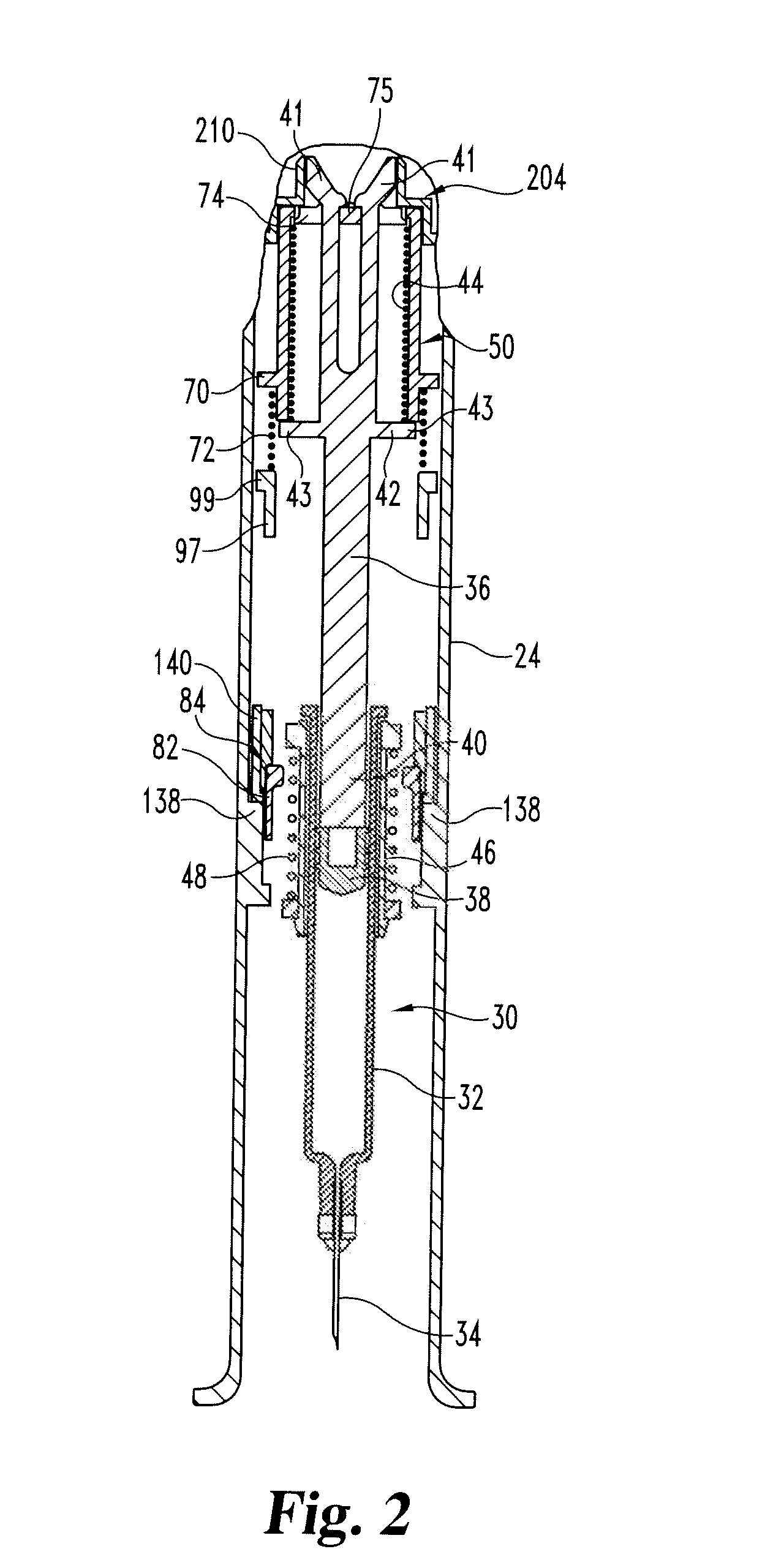
[0045]Referring now to FIGS. 1 and 2, there are respectively shown a front view and a partial, cross-sectional front view of an automatic injection apparatus equipped with a first embodiment of a delay mechanism of the present invention. As delay mechanisms of the present invention advantageously may be employed in a variety of differently configured automatic injection apparatuses, only limited injection apparatus details are shown and described herein, and such details are intended to be illustrative and not limiting in any way.

[0046]As is conventional, the automatic injection apparatus, generally designated 20, has a trigger that when actuated by a user results in the needled syringe of the apparatus being driven downward such that the injection needle projects beyond the bottom end of the apparatus housing to penetrate the user. The apparatus then proceeds to inject the medication contents of the syringe through the needle, after which the syringe is retracted such that the inje...


PUM


Abstract

A delay mechanism for staging the operation of an automatic injection apparatus (20) to ensure medication contents are properly delivered prior to the needled syringe (32) of the apparatus being retracted. In one form, the delay mechanism includes a shuttle (50), a follower (110), a locking member, a damping compound, and a driver and a driver biasing element (44). The shuttle is for a needled syringe of the apparatus and includes a first latching element. The follower includes a second latching element and a cammable surface, which second latching element is for cooperating with the first latching element to limit motion of the shuttle relative to the follower in a second direction opposite the first direction. The locking member is movable from a locking position to a release position by engagement with the syringe plunger during an injection, the locking member, when in the locking position, preventing rotation of the follower relative to the shuttle, the locking member, when in the release position, allowing rotation of the follower relative to the shuttle. The damping compound is between the follower and a supporting surface to dampen rotation of the follower relative to the shuttle. The driver is rotatably fixed relative to the shuttle and includes a camming surface. The shuttle allowing retracting of the syringe needle into the housing of the automatic injection apparatus after injection.

Description

BACKGROUND OF THE INVENTION[0001]The present invention pertains to pharmaceutical injection devices, and, in particular, to a delay mechanism for an automatic injection device.[0002]Patients suffering from a number of different diseases frequently must inject themselves with pharmaceuticals. A variety of devices have been proposed to facilitate these injections. One type of device is an automatic injection device. This type of device, when triggered by a user, automatically inserts into the user a needle of a syringe that prior to triggering was disposed within the device housing, and then automatically injects a dose of medication through that inserted needle. One known type of automatic injection device then automatically advances a shroud to cover the needle when the dose is completed. In another type of automatic injection device having a configuration more desirable to some, and instead of having an advancing shroud, the device will automatically retract the needle into the hou...

Claims


Application Information

Patent Timeline
IPC IPC(8): A61M5/50
CPCA61M5/2033A61M5/3202A61M5/3204A61M2005/3143A61M2005/206A61M2005/2073A61M5/326A61M5/32A61M5/20
Inventor JAMES, ADRIAN BENTONLISTER, ROBERT IANSILBERSCHATZ, PAUL JOSEPHMASON, BRIAN JOSEPH
Owner ELI LILLY & CO
Why Eureka
Try Eureka