System and GUI for specifying composite predicates and dynamic systems

a dynamic system and composite predicates technology, applied in the field of system and gui for specifying composite predicates and dynamic systems, can solve the problems of complex behavior with lots of parallel activities, such as a business process, which cannot be easily described in a textual language, and flowcharts have their own limitations, so as to improve the complexity of decisions

Inactive Publication Date: 2010-02-25
SHIA DANIEL
View PDF6 Cites 4 Cited by
  • Summary
  • Abstract
  • Description
  • Claims
  • Application Information

AI Technical Summary

Benefits of technology

[0018]Another purpose is to improve how complex decisions or conditions, which may have multiple parameters and multiple results, are specified.

Problems solved by technology

Due to the sequential nature of a text based computer language, a complex behavior with lots of parallel activities, such as a business process, cannot be easily described in a textual language.
However, a flowchart has its own limitations.
Although there are lots of improvement over the flowchart, these new graphical languages share one common weakness with the flowchart, that is the description of a complex decision or condition is still based on a textual expression.
However, when describing a complex condition, which requires using logical “AND” or “OR” operators to combine multiple simple expressions, a text based boolean expression is not entirely satisfactory for several reasons.
First, the behavior of a text based, complex boolean expression may be counter-intuitive, since the evaluation sequence relies on some implicit precedence rules.
Second, a text based boolean expression can only operate on two operands at a time, hence, cannot operate on multiple operands simultaneously.
In addition, since only two operands are evaluated at one time, some undesirable side effects may be produced unintentionally by repeatedly applying these operators.
It is not suitable for specifying a decision where multiple choices need to be selected simultaneously.
However, for relatively complex conditions, writing multiple long boolean expressions would be tedious.
Fifth, the complex decision logic and conditions cannot be shown in graphics like the rest of the behavior specifications.
Since the decision logic is a fundamental part of any complex behavior, by keeping the complex decision logic in a text form, full graphical representation of the behavior of a computing system cannot be accomplished.

Method used


Image

  • System and GUI for specifying composite predicates and dynamic systems
  • System and GUI for specifying composite predicates and dynamic systems
  • System and GUI for specifying composite predicates and dynamic systems

Examples


Embodiment Construction

[0080]The present invention in the form of one or more exemplary embodiments will now be described. In the following description, numerous specific details are set forth in detail to provide a more thorough description of the invention. It will be apparent to one skilled in the art, however, that this invention can be practiced without these specific details. In other instances, well known features have not been described in detail so as not to unnecessarily obscure the invention.

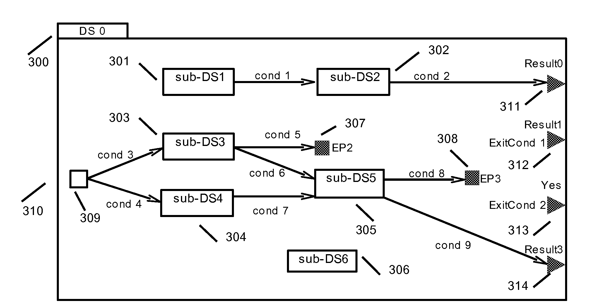
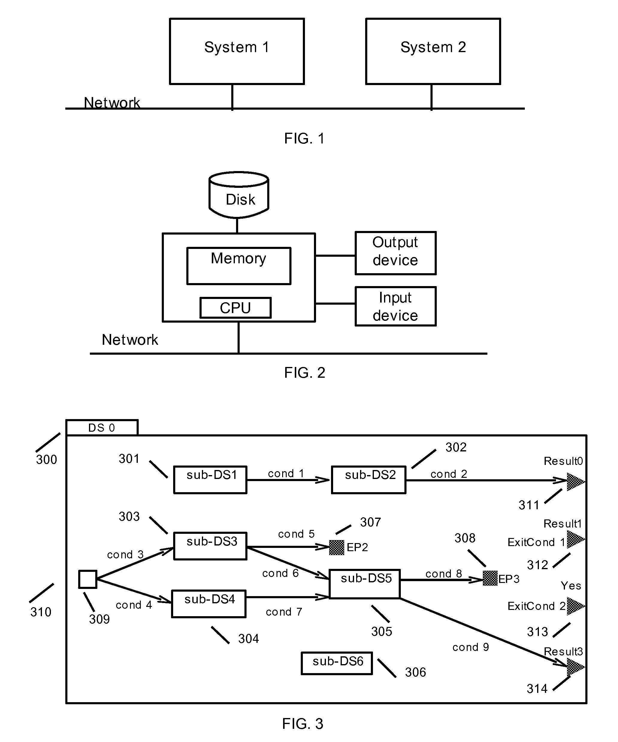
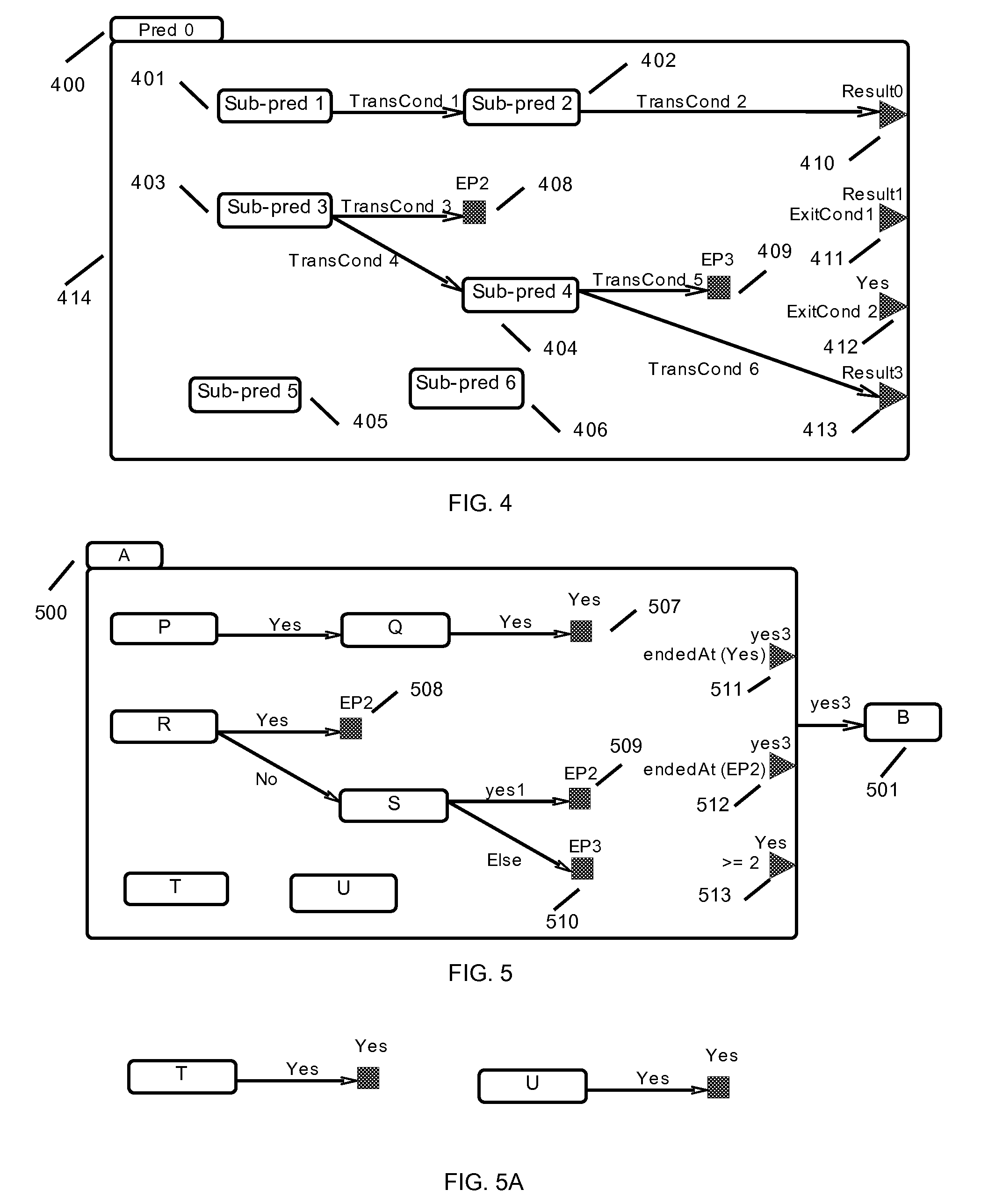
[0081]Many computing systems have complex behaviors. This invention uses the Dynamic-System (DS) construct to describe the internal behavior of these computing systems. In order to display the internal behavior of a computing system to human users, some graphical languages are provided in this invention as man-machine interface to facilitate the understanding of the complex behavior being described. A design tool may use one of these graphical languages to allow a user to specify the behavior of a computing...


PUM


Abstract

System for specifying the behavior of a composite predicate and a composite dynamic system, and procedures about their operations are provided in the present invention. While a composite predicate is provided to check for a complex condition when a decision is made in a computing system, a composite dynamic system is provided for specifying the behavior of the entire computing system. In addition, a graphical language is provided for showing composite predicates and dynamic systems in graphical diagrams. Some existing graphical languages, such as BPMN and UML Activity Diagrams, are extended with similar capabilities.

Description

PRIORITY CLAIM / RELATED CASE[0001]This application claims priority under 35 U.S.C. 119(e) to U.S. Provisional Patent Application Ser. No. 60 / 993,258, filed on Sep. 11, 2007 and entitled “SYSTEM AND GUI FOR SPECIFYING COMPOSITE PREDICATES AND DYNAMIC SYSTEMS”, which is incorporated herein by reference in its entirety for all purposes.FIELD OF THE INVENTION[0002]The present invention relates to the design of graphical notation or language for describing predicates, boolean expressions, conditional expressions, flow controls, activities, business processes, and system behaviors and their implementations in software tools.BACKGROUND OF THE INVENTION[0003]Due to the sequential nature of a text based computer language, a complex behavior with lots of parallel activities, such as a business process, cannot be easily described in a textual language. For half an century, flowcharts have been used to overcome this weakness of a textual language. However, a flowchart has its own limitations. In...

Claims


Application Information

Patent Timeline
Patent Type & Authority Applications(United States)
IPC IPC(8): G06F3/048
CPCG06Q10/06G06F8/10
Inventor SHIA, DANIEL
Owner SHIA DANIEL
Why Eureka
Try Eureka