Piezoelectric windmill apparatus

a windmill and piezoelectric technology, applied in the field of ceramic materials, can solve the problems of high inefficiency of such electromagnetic generators on a small scale, ineffective use of conventional electromagnetic generators for scale energy production, and insufficient realization of the potential for small scale energy production from wind flow

Inactive Publication Date: 2010-03-04
BOARD OF REGENTS
View PDF21 Cites 86 Cited by
  • Summary
  • Abstract
  • Description
  • Claims
  • Application Information

AI Technical Summary

Problems solved by technology

However, use of such electromagnetic generators is highly inefficient on a small scale.
As such, conventional electromagnetic generators are not efficient for scale energy production from wind flow at small speeds.
To date, the potential for small scale energy production from wind flow has not been fully realized.
At these speeds, the force generated from small size vanes is very small (<0.1 N), which makes the use of any k

Method used


Image

  • Piezoelectric windmill apparatus
  • Piezoelectric windmill apparatus
  • Piezoelectric windmill apparatus

Examples


Embodiment Construction

[0030]Although making and using various embodiments of one embodiment are discussed in detail below, it should be appreciated that one embodiment provides many inventive concepts that may be embodied in a wide variety of contexts. The specific aspects and embodiments discussed herein are merely illustrative of ways to make and use the invention, and do not limit the scope of the invention. In the description which follows like parts may be marked throughout the specification and drawing with the same reference numerals, respectively. The drawing figures are not necessarily to scale and certain features may be shown exaggerated in scale or in somewhat generalized or schematic form in the interest of clarity and conciseness.

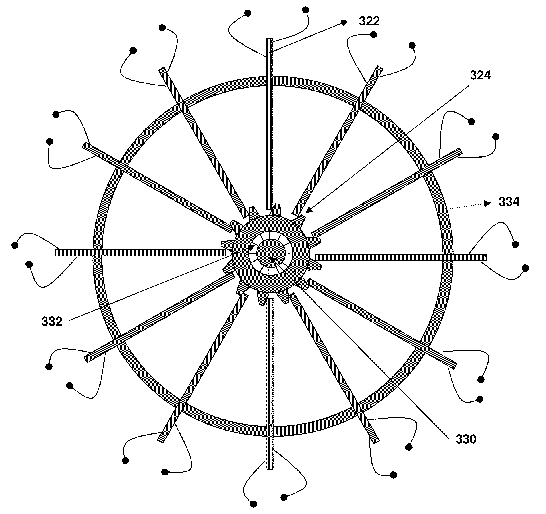
[0031]In one embodiment, the piezoelectric windmill apparatus 300 uses wind energy for electric-power generation, because wind provides a constant source of mechanical energy as opposed to other sources that are often random and difficult to control. In one embodim...


PUM

PropertyMeasurementUnit
Electric energyaaaaaaaaaa
Energyaaaaaaaaaa

Abstract

A piezoelectric windmill configured to handle small scale wind flow. One embodiment the piezoelectric windmill solves problems associated with harvesting energy and generating electric energy or power using piezoelectric materials having significant advantages over previously available materials.

Description

CROSS-RELATED APPLICATIONS[0001]The present application is a continuation-in-part of U.S. application Ser. No. 11 / 252,923, filed Oct. 18, 2005, which is incorporated by reference herein.BACKGROUND OF THE INVENTION[0002]One embodiment relates generally to ceramic materials, in particular, ceramic materials piezoelectric coupled with windmill-like devices.[0003]Large scale electrical power is presently produced through various techniques including converting wind flow to electrical energy. Energy production from wind flow is typically accomplished by means of a windmill transferring a rotational force to an electromagnetic generator. Conventional electromagnetic generators employ a moving coil of electrically conducting material in a magnetic field. Normally the electrical conductor is a copper (or aluminum) wire. As is well known in the art, the movement of a coil of electrically conducting material in a magnetic field produces an electric current. This effect is commonly referred to...

Claims


Application Information

Patent Timeline
IPC IPC(8): F03D9/02H02N2/18F03D9/00
CPCC04B35/493C04B2235/3251C04B2235/3262C04B2235/3284Y02E10/725F05B2220/709H01L41/1136H01L41/1876H02N2/18F03D9/002F03D9/25B33Y80/00F03D15/10F03D9/11Y02E10/72Y02E70/30H10N30/306H10N30/8554
Inventor PRIYA, SHASHANK
Owner BOARD OF REGENTS
Why Eureka
Try Eureka