Test socket and test module

Inactive Publication Date: 2010-03-04
KING YUAN ELECTRONICS
View PDF2 Cites 6 Cited by
  • Summary
  • Abstract
  • Description
  • Claims
  • Application Information

AI Technical Summary

Benefits of technology

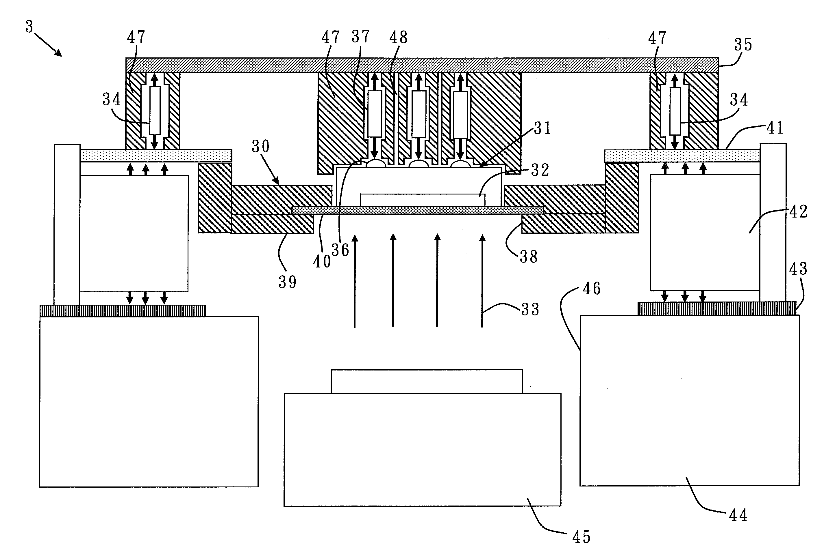
[0013]An object of the present invention is to provide a novel test socket and a test module for preventing an uneven illumination or shadowing of the sensing area, as well as reducing cost and increasing efficiency.

Problems solved by technology

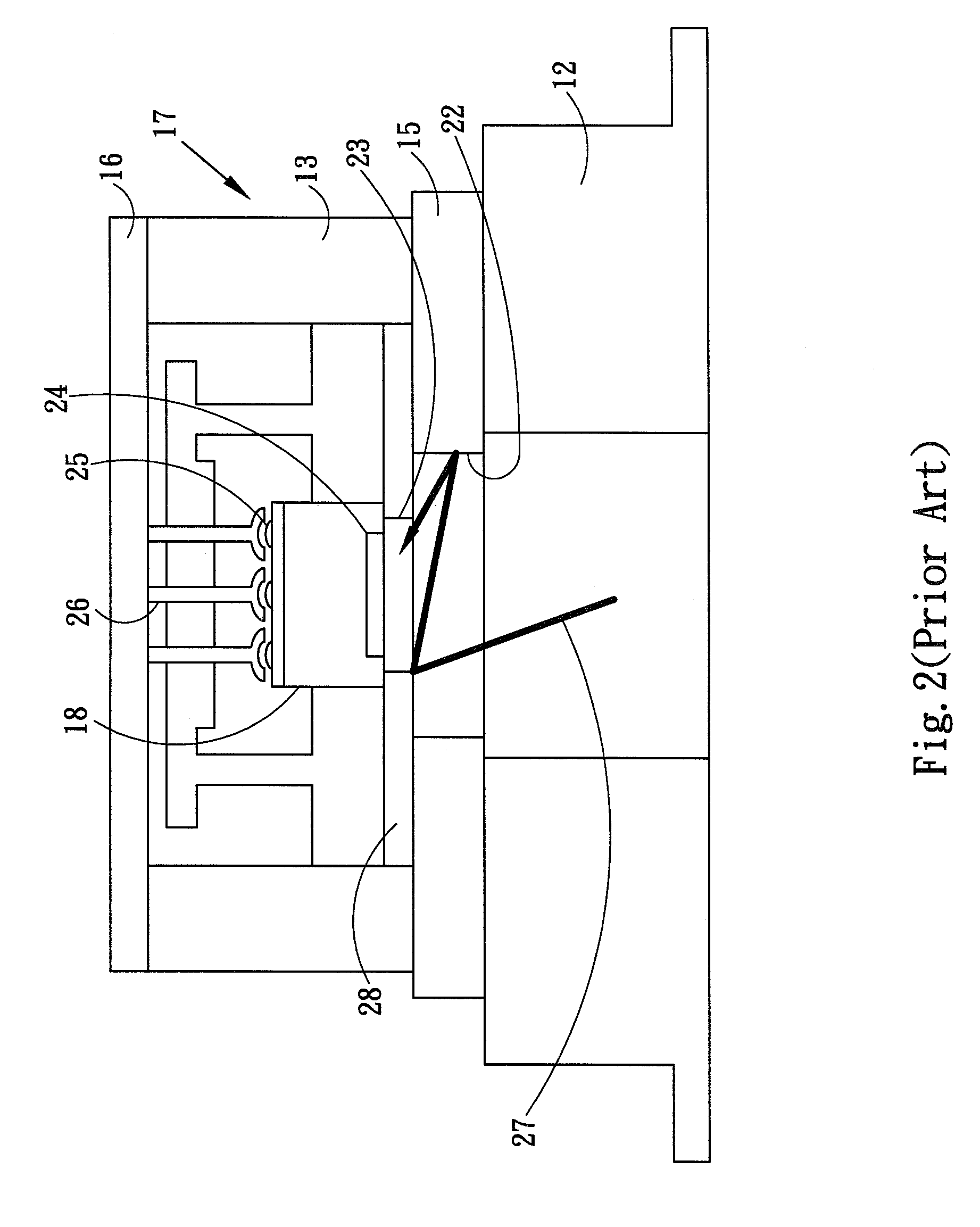
This will also contribute to the uneven illumination or shadowing of the sensing area.
This will waste time and increase cost.

Method used


Image

  • Test socket and test module
  • Test socket and test module
  • Test socket and test module

Examples


Embodiment Construction

[0020]The detailed description of the present invention will be discussed in the following embodiments, which are not intended to limit the scope of the present invention, but can be adapted for other applications. While drawings are illustrated in details, it is appreciated that the quantity of the disclosed components may be greater or less than that disclosed, except expressly restricting the amount of the components. Wherever possible, the same or similar reference numbers are used in drawings and the description to refer to the same or like parts. It should be noted that any drawings presented are in simplified form and are not to precise scale. In reference to the disclosure herein, for purposes of convenience and clarity only, directional terms, such as, top, bottom, left, right, up, down, over, above, below, beneath, rear, and front, are used with respect to the accompanying drawing. Such directional terms should not be construed to limit the scope of the invention in any ma...


PUM


Abstract

The present invention discloses a test socket for testing an image sensor that comprises a sensing area facing a light source. The test socket comprises a signal-connecting mechanism for transmitting a signal between the image sensor and a source of the test signal, a bearing layer having an opening and being arranged at the surface facing the light source, and a transparent layer arranged between the image sensor and the bearing layer for supporting the image sensor.

Description

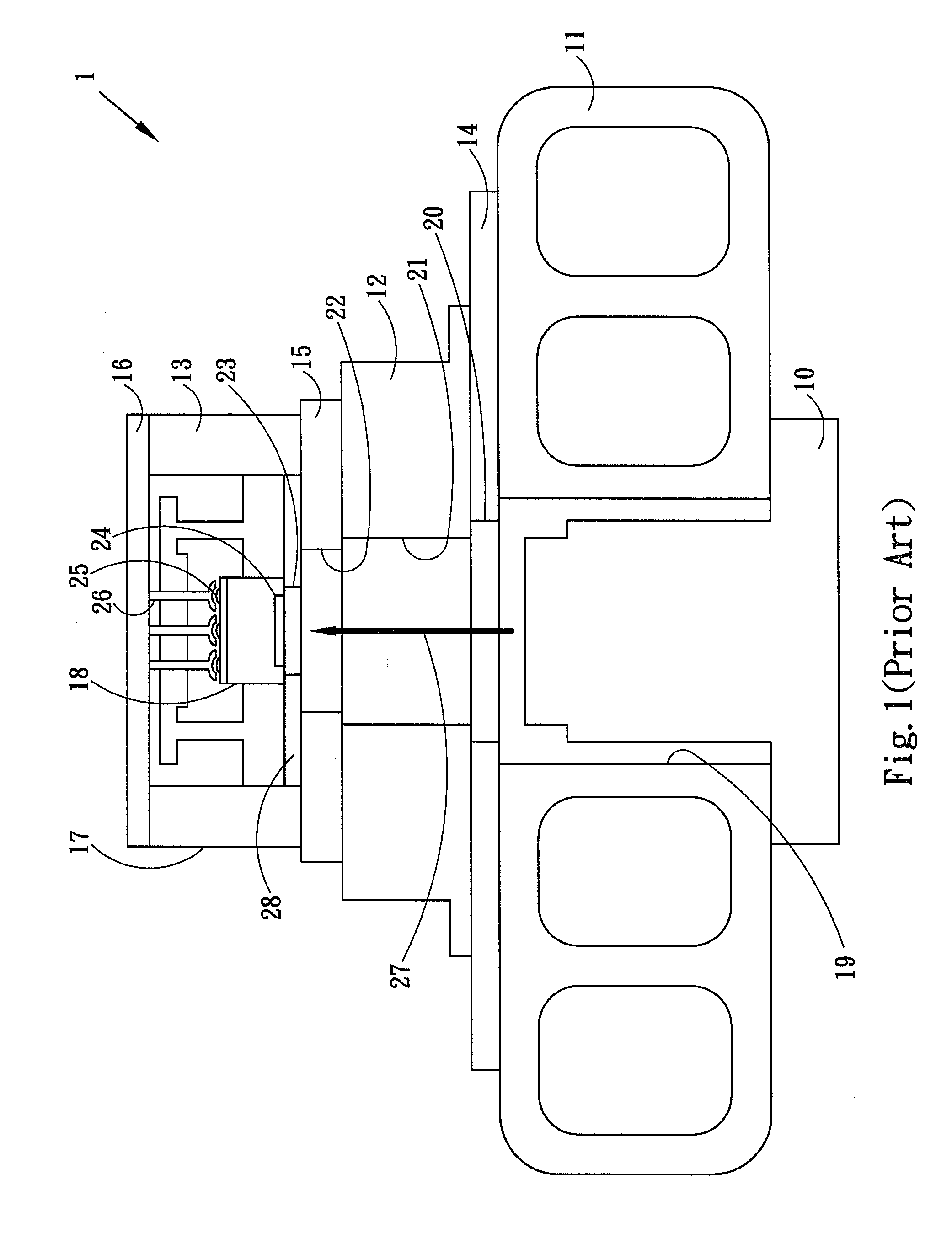
BACKGROUND OF THE INVENTION[0001]1. Field of the Invention[0002]The present invention relates to a test socket and a test module, and more particularly, to a test socket and a test module of an image sensor.[0003]2. Description of the Prior Art[0004]An image sensor such as a Complementary Metal-Oxide-Semiconductor (CMOS) or a Charge-Coupled Device (CCD) will proceed with a final test after the packaging is finished.[0005]FIG. 1 shows a conventional test module for the final test of an image sensor. For testing an image sensor 18, the test module 1 comprises a light source 10, a test head 11, a plurality of pogo-pins 13, a pogo-tower 12, a signal board 16, a test board 15, a load board 14, and a test socket 17.[0006]The light source 10 is arranged at an opening 19 of the test head 11; when testing, the light source 10 irradiates a smooth, uniform light 27 sequentially transmitted through an opening 20 of the load board 14, an opening 21 of the pogo-tower 12, an opening 22 of the test...

Claims


Application Information

Patent Timeline
IPC IPC(8): G01R31/28
CPCG01R1/0433H01R33/76
Inventor CHANG, CHIU-FANG
Owner KING YUAN ELECTRONICS
Why Eureka
Try Eureka