
Method and system for universal lane boundary detection

a technology of universal lane boundary and detection method, applied in the field of video image processing, can solve the problems of failure of approaches using known marking size, failure of approaches using hough transform, failure of approaches using the continuity of the stripe,

Active Publication Date: 2010-03-04
VALEO SCHALTER & SENSOREN
View PDF9 Cites 107 Cited by
  • Summary
  • Abstract
  • Description
  • Claims
  • Application Information

AI Technical Summary

Benefits of technology

The present invention provides a method and system for detecting road markings, such as lane markings or road boundaries. The system includes an image processor and a road marking detection module. The image processor receives an image of a road and identifies a region of interest in the image. The road marking detection module detects lane markings and road boundaries by analyzing the image. The system uses edge strength and gradient thresholds to identify potential road marking edges and compares them to pre-defined lines to determine if they fit the image. The system can also detect road boundaries based on the spacing between edges. The technical effect of this invention is to provide a reliable and accurate method for detecting road markings, which can be used in various applications such as autonomous vehicles.

Problems solved by technology

Approaches using the continuity of the stripe fail when the markings are of the Botts dots type (domed, white, disks about 10 cm in diameter) or reflectors, which do not provide a sufficiently continuous signal.
Approaches using the known size of the markings fail when the marking has a different size.
Finally, approaches using a Hough transform fail in difficult conditions (such as multiple, parallel, markings, where more than one solution exists) and require significant computation power.
However, vertical edge detection fails in curves, where the markings appear at a significant angle.

Method used


Image

  • Method and system for universal lane boundary detection
  • Method and system for universal lane boundary detection
  • Method and system for universal lane boundary detection

Examples


Embodiment Construction

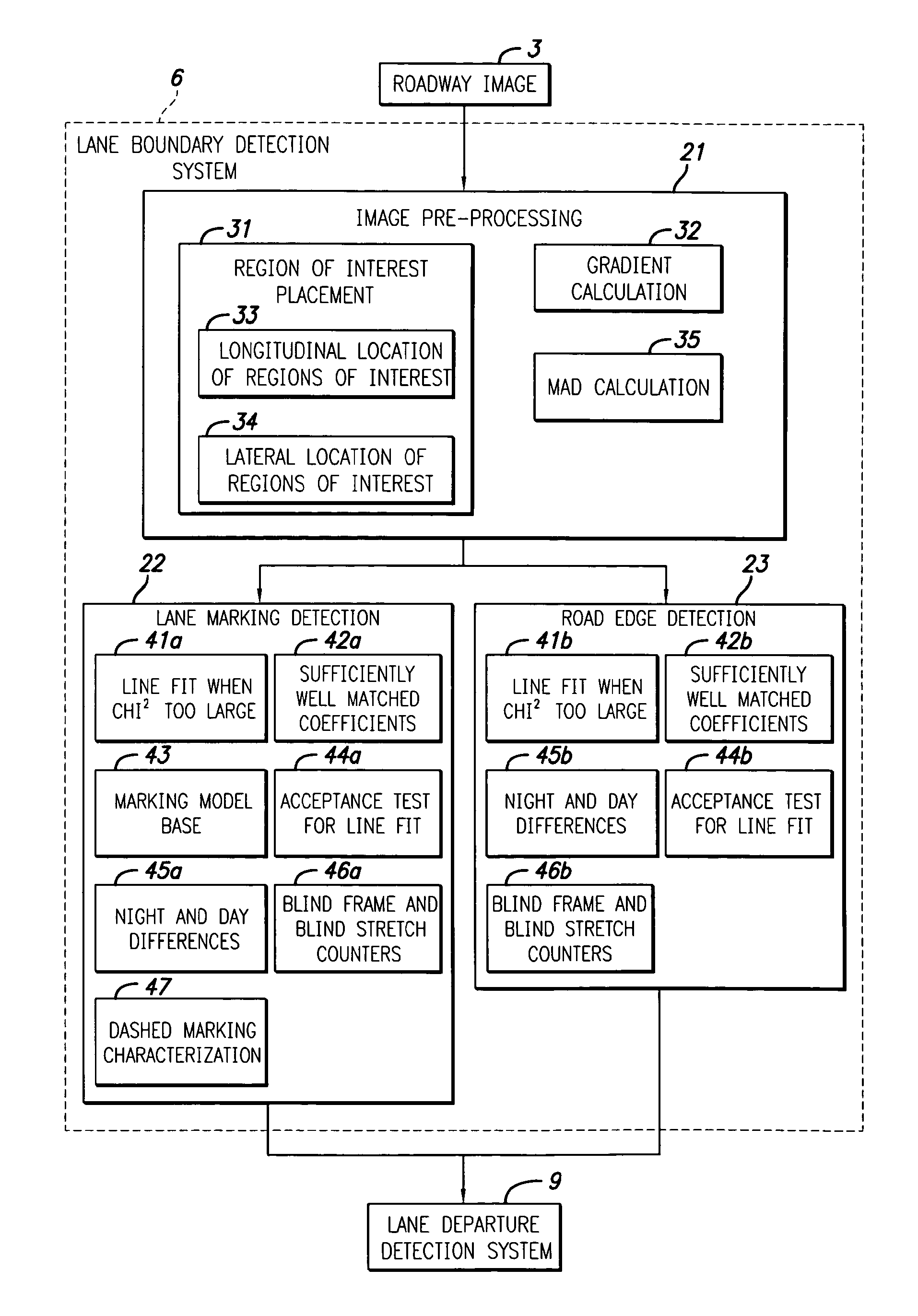
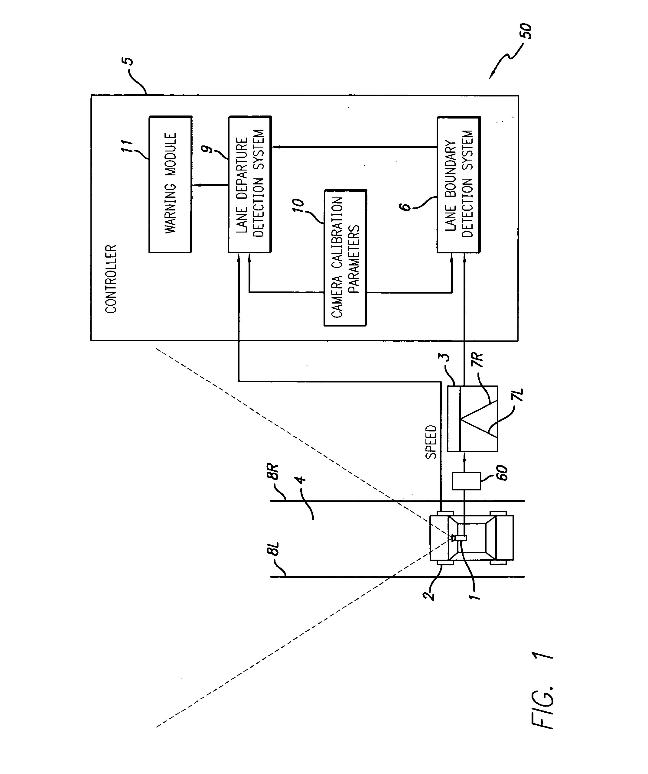
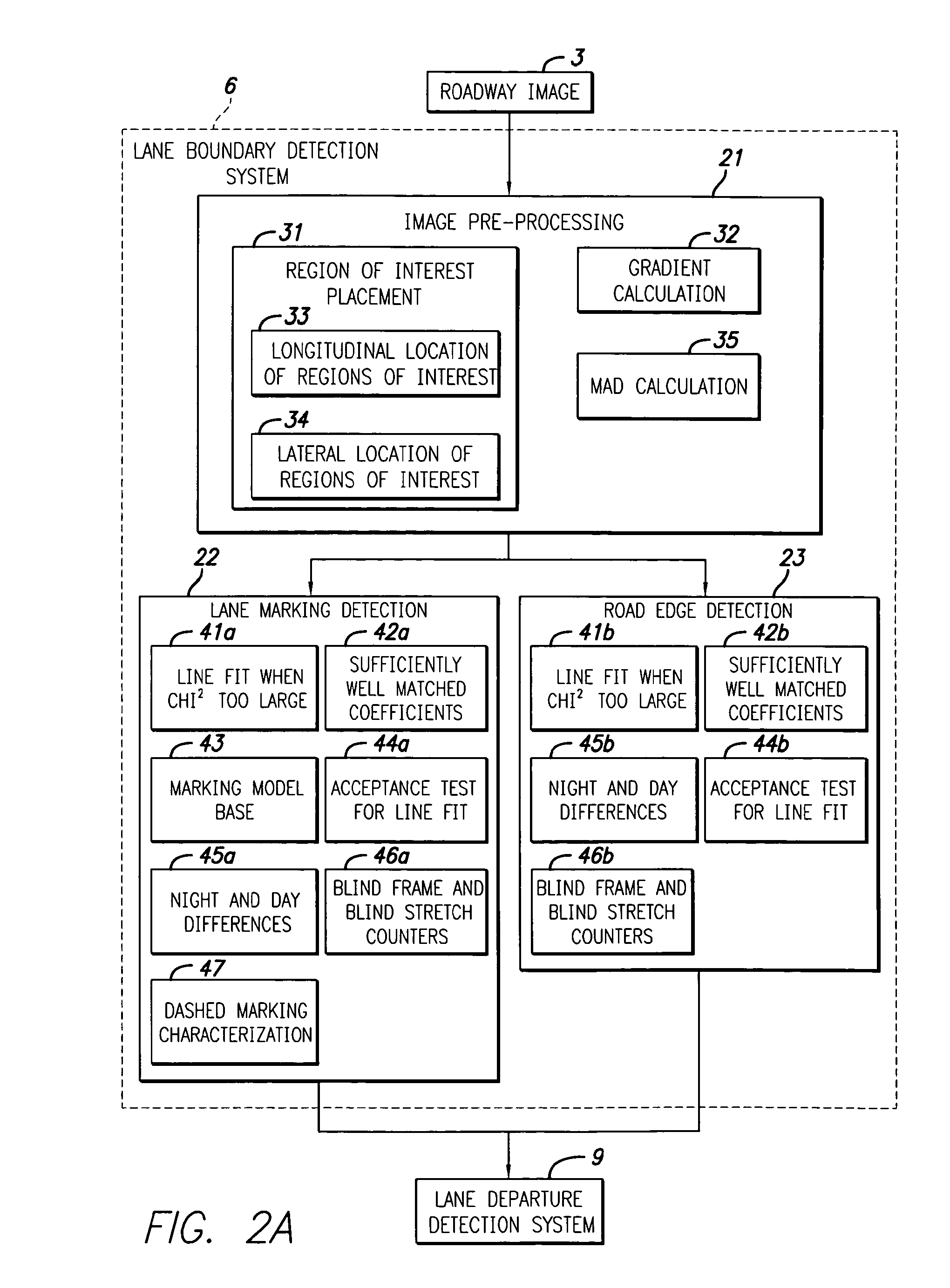
[0032]The present invention provides a method and system for universal lane boundary detection. One embodiment involves finding road markings including lane markings or road boundaries of a driving lane or road, using a video image of the lane or road. This is achieved by searching a video image region for significant gradients (e.g., luminance gradient) bordering image features of at least a minimum and up to a maximum size. The gradient search may be performed in the gray level image or in a mean absolute deviation image. The locations of the gradients are grouped together with curve fitting (choosing subsets, if needed) to obtain a proper fit quality and consistency. The curve fit features represent lane markings or road boundaries. An oriented and paired process finds lane markings, while an unpaired process finds road boundaries. A sequence of steps is used to find both stripe and simple edge type boundaries, passing multiple times through different versions or subsets of the s...


PUM


Abstract

A method and system for detecting road markings, is provided. One implementation involves receiving an image (3) of a road (4) in front of a vehicle (2) from an imager (1), determining a region of interest in an identified road in the image, and detecting road markings (8L1 8R) by detecting lane markings (7L, 7R) in the region of interest, and if lane markings cannot be detected, then detecting road boundaries in the region of interest.

Description

RELATED APPLICATIONS[0001]This application claims priority under 35 U.S.C. 119(e) from U.S. Provisional Patent Application Ser. No. 60 / 897,082, filed Jan. 23, 2007, incorporated herein by reference. This application further claims priority under 35 U.S.C. 119(e) from U.S. Provisional Patent Application Ser. No. 60 / 897,225, filed Jan. 23, 2007, incorporated herein by reference. This application further claims priority under 35 U.S.C. 119(e) from U.S. Provisional Patent Application Ser. No. 60 / 897,219, filed Jan. 23, 2007, incorporated herein by reference. This application further claims priority under 35 U.S.C. 119(e) from U.S. Provisional Patent Application Ser. No. 60 / 897,220, filed Jan. 23, 2007, incorporated herein by reference.FIELD OF THE INVENTION[0002]The present invention relates to video image processing and in particular to detecting roadway features in video images.BACKGROUND OF THE INVENTION[0003]A detection system coupled to a video camera can be used to locate road lan...

Claims


Application Information

Patent Timeline
Patent Type & Authority Applications(United States)
IPC IPC(8): G06K9/00E01F9/06
CPCG06K9/00798G06T7/2033G06T7/60G06T7/246G06V20/588
Inventor BOON, CATHY
Owner VALEO SCHALTER & SENSOREN
Learn More