
Electromagnetic interference alarm

Inactive Publication Date: 2010-03-04
MEDTRONIC INC
View PDF3 Cites 7 Cited by
  • Summary
  • Abstract
  • Description
  • Claims
  • Application Information

AI Technical Summary

Benefits of technology

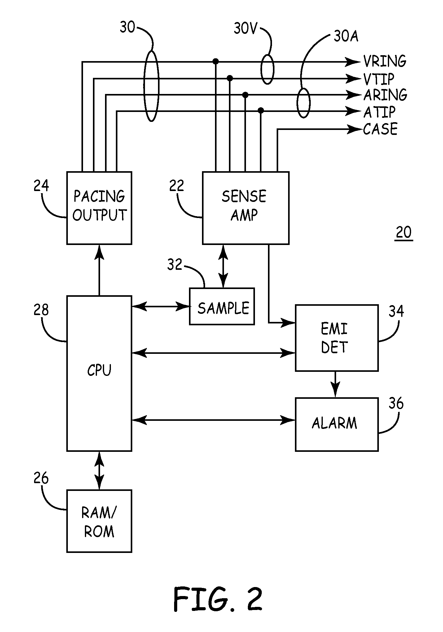
[0010]An apparatus and method are provided for detecting non-physiologic electromagnetic interference (EMI) to an implantable medical device (IMD) and for warning the user of the device of the danger of remaining in the vicinity of the source of the EMI, such that the patient could move away from the area to restore proper operation of the pacemaker. The apparatus comprises an implantable medical device electrically coupled to a patient, having a sensor for sensing physiologic conditions and circuitry coupled to the sensor for providing therapy in response to sensed physiologic conditions. A detector is coupled to the device for detecting the presence of electromagnetic interference and an alarm is coupled to the detector to signal the patient of the implantable medical device of the presence of electromagnetic interference and the intensity thereof and to assist the patient in avoiding the area of disruptive EMI.

Problems solved by technology

The presence of electromagnetic interference (EMI), if the field is large enough, can compromise the cardiac sensing function such that the pacemaker may fail to deliver a needed therapy or may deliver an unwanted therapy.
There is no way to single out this interference.
However, if large enough they can block the sensing of the physiologic signals and leave the device without the needed information to reliably treat the heart.
Other sources of disruptive interference can also compromise the sensing of the physiologic signals by an IMD.
This may not be optimal therapy.
Among the complications are; the fixed rate may cause an arrhythmia in some patients; or in the case of tachycardia therapies the device may miss the need for delivery of a therapy.
In the past however such devices and methods have provided only a simple alarm that, although providing a warning to a patient that he has entered an area in which EMI may affect the functioning of his IMD, these devices and methods did not assist the patient in moving to an area where EMI is not problematical.

Method used


Image

  • Electromagnetic interference alarm
  • Electromagnetic interference alarm
  • Electromagnetic interference alarm

Examples


Embodiment Construction

[0016]The following detailed description of the invention is merely exemplary in nature and is not intended to limit the invention or the application and uses of the invention. Furthermore, there is no intention to be bound by any theory presented in the preceding background of the invention or the following detailed description of the invention.

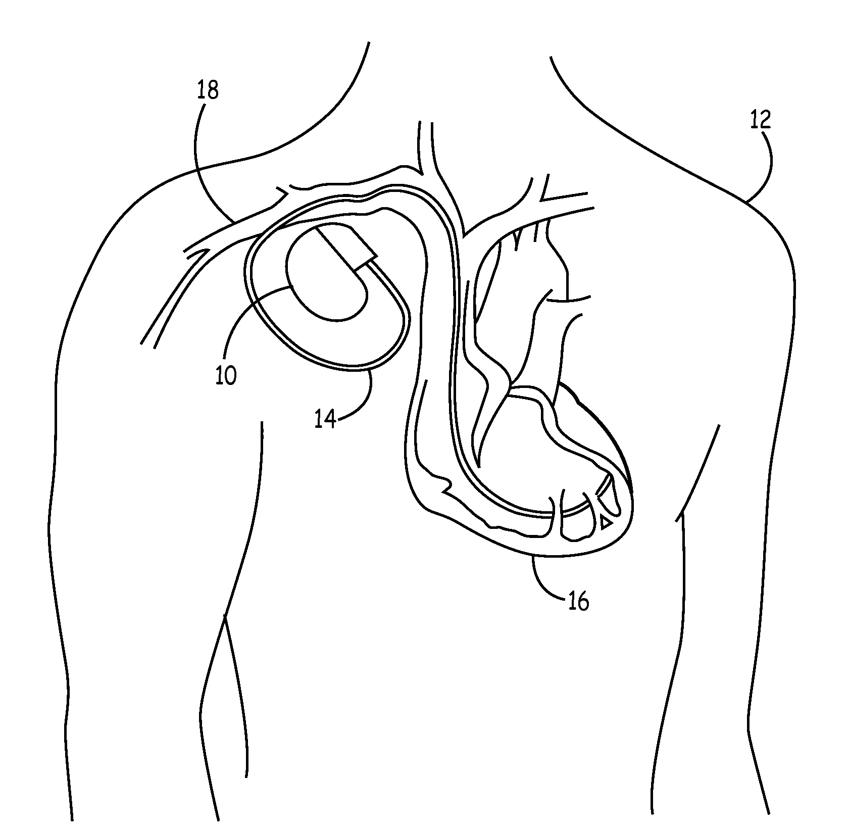
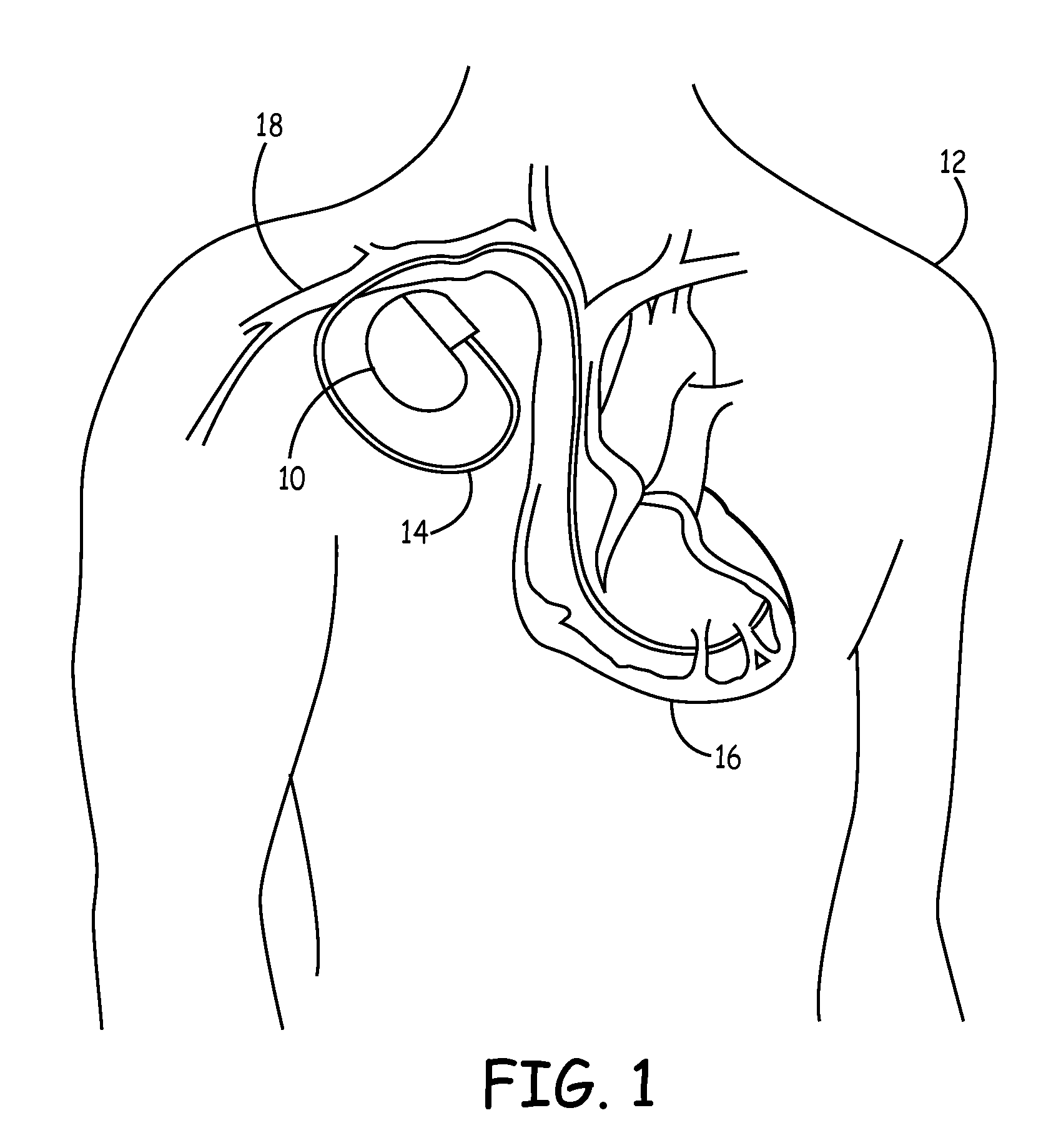
[0017]FIG. 1 is an illustration showing generally where an implantable medical device (IMD) 10 is placed in a conventional manner in a patient 12. IMD 10 is conventionally housed within a hermetically sealed, biologically inert outer canister, which itself may be of a conductive material and serve as an electrode in the IMDs pacing / sensing circuit. One or more leads, collectively identified as 14 are electrically coupled to IMD 10 in a conventional manner, extending into the patient's heart 16 via a vein 18. Disposed generally near the distal end of lead 14 are one or more exposed conductive electrodes for receiving electrical cardiac signal...


PUM


Abstract

An apparatus and method are disclosed including an implantable medical device electrically coupled to a patient, having a sensor for sensing physiologic conditions and circuitry coupled to the sensor for emitting therapy in response to sensed physiologic conditions. A detector is coupled to the cardiac device for detecting the presence of electromagnetic interference and the intensity thereof and an alarm is coupled to the detector to signal the patient of the implantable medical device of the presence of electromagnetic interference.

Description

CROSS-REFERENCE TO RELATED APPLICATIONS[0001]This application is a divisional of U.S. patent application Ser. No. 10 / 449,428 filed on May 30, 2003. The disclosure of the above application is incorporated herein by reference.FIELD OF THE INVENTION[0002]The present invention generally relates to electromagnetic interference alarms, and more particularly relates to electromagnetic interference alarms in implantable medical devices.BACKGROUND OF THE INVENTION[0003]An implantable medical device (IMD) may be a device such as an implantable pulse generator (IPG), commonly referred to as a pacemaker, which is used to stimulate the heart into a contraction if the sinus node of the heart is not properly timing, or pacing, the contractions of the heart. Modern cardiac devices also perform many other functions beyond that of pacing. For example, some cardiac devices such as implantable cardioverter-defibrillators (ICDs) may also perform therapies such as defibrillation and cardioversion as well...

Claims


Application Information

Patent Timeline
IPC IPC(8): A61N1/08A61N1/37
CPCA61N1/3718A61N1/37
Inventor BALLIS, JOSEPH J.
Owner MEDTRONIC INC
Learn More