Crown extrusion

a crown molding and extrusion technology, applied in the field of decorative moldings, can solve the problems of difficult application of crown molding, room corners, and exacerbated problems associated with crown molding installation

Inactive Publication Date: 2010-03-11
ROWOHLT TODD
View PDF29 Cites 6 Cited by
  • Summary
  • Abstract
  • Description
  • Claims
  • Application Information

AI Technical Summary

Benefits of technology

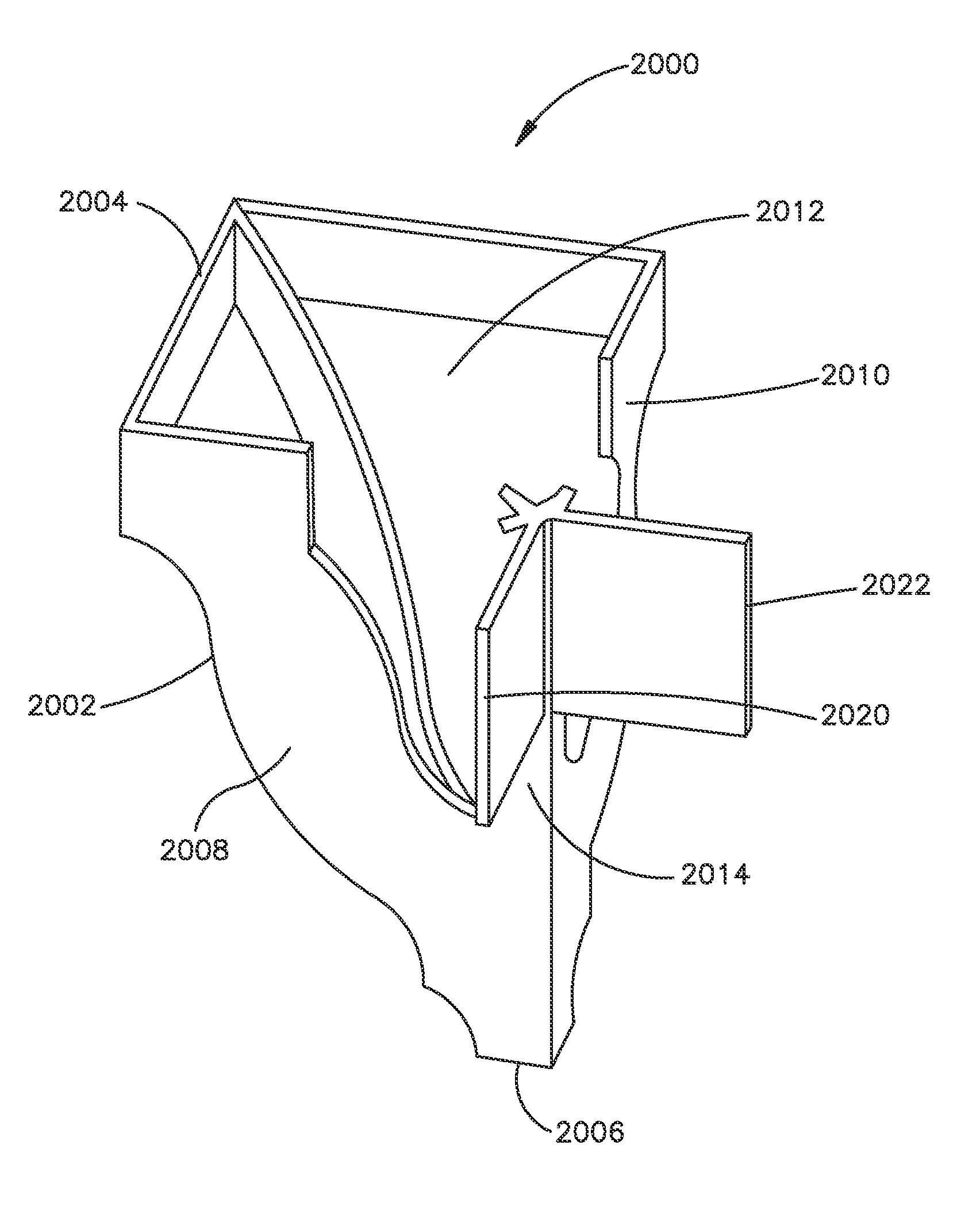
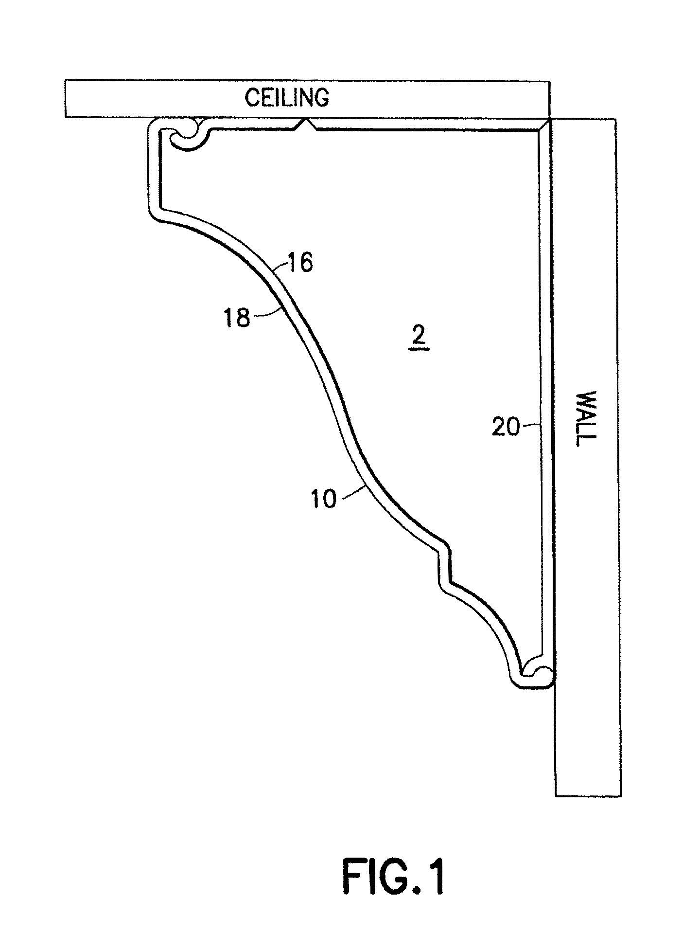
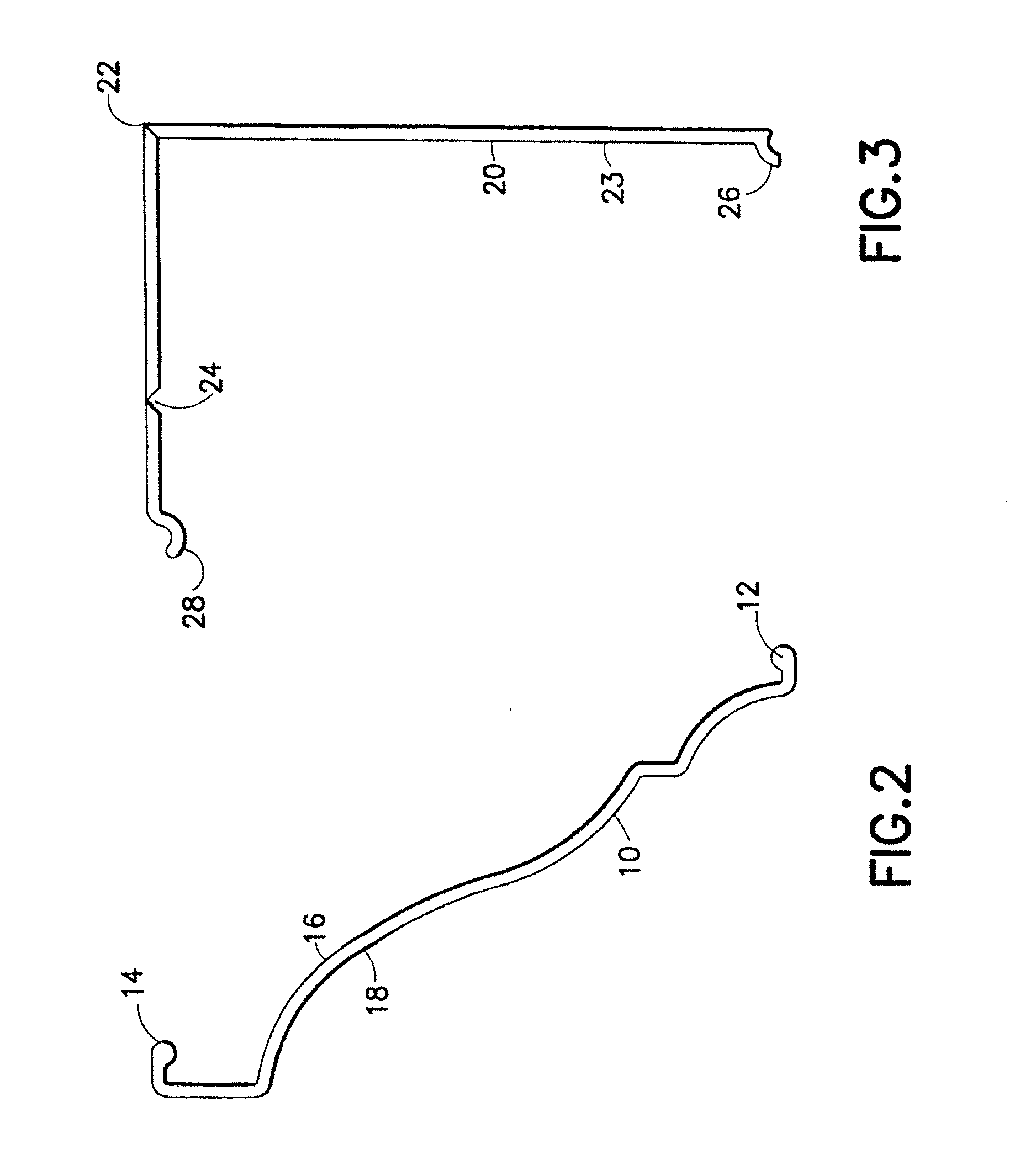
[0009]In an embodiment of the present invention, a decorative molding system and method of installation includes a pair of removably engagable molding components. Specifically, a base piece includes a run member hingeably connected to a rise member, such that an approximately 90-degree angle can be created between the run and rise members. Each of the run and rise members include an engagement hook at their respective ends. The base piece is mounted to vertical wall and ceiling surfaces by attaching the run member to the ceiling and the rise member to the wall, such that the hinge portion connecting the run and rise members sits approximately in the intersection between the vertical wall and ceiling. A molding piece having a decorative surface generally of a profile known in the art for crown moldings includes upper and lower engagement surfaces. Each of the upper and lower engagement surfaces includes a protrusion for engagement with the engagement hooks on the base piece. In this way, the molding piece can be removably engaged to the base piece to give an appearance similar to traditional crown molding, but with an ease of installation unavailable with traditional crown molding.
[0010]In this embodiment, the base piece and crown piece are removably engagable to each other and can be flush mounted to the ceiling. In another embodiment, the system is adapted to provide mounting that is not flush with the ceiling for decorative and visual effect, and possibly to be combined with a secondary visual element. In this embodiment, the hinge connecting the run and rise members is designed such that its rotation about an axis passing through the hinge will not rotate substantially past a point creating an angle smaller than approximately 90-degrees between the run and rise members. As such, the base piece can be fixed to a vertical wall via the rise member without attachment of the run member such that the molding can be attached to provide a space between the ceiling and top of the molding. The base piece may further include vents or a channel in the surface of the run member enabling the routing of accent lighting.
[0011]In yet another embodiment, either or both of the base and crown pieces can be provided in a form, such as but not limited to a roll, that enables a user of the system to cut the respective pieces required for a specific length to avoid splicing together separate pieces to cover a given wall space. In this embodiment, the system may be extruded or formed using plastic so that it can be coiled or rolled during the forming process. Therefore, the user is not limited to any specific length or span and the need for “splicing” two spans together is rendered obsolete. The base piece of the system may be mounted to a wall or ceiling surface using any of a number of fasteners, including but not limited to nails, screws, adhesives, adhesive tapes, and the like. The base piece may also include at one or more secondary hingeable portions disposed on either or both of the run and rise members to facilitate bending of the base piece to conform to the contour of the juncture of a wall and ceiling thereby improving installation on walls and ceilings that may be out of square.
[0012]Additionally, in some embodiments, the crown molding systems are significantly lighter as a result of the thickness of the crown profile and the materials from which the molding pieces are formed. Furthermore, in accordance with at least one embodiment, the system requires only a standard utility knife and fastener. Specifically, the ends of the crown piece can be mitered using a utility knife to form the corners.
[0014]In yet another embodiment of the present invention, a decorative molding system and method of installation includes a pair of removably engagable molding components. Specifically, a base piece includes a run member hingeably connected to a rise member, such that an approximately 90-degree angle can be created between the run and rise members. Each of the run and rise members include an engagement member at their respective ends. The base piece is mounted to vertical wall and ceiling surfaces by attaching the run member to the ceiling and the rise member to the wall, such that the hinge portion connecting the run and rise members sits approximately in the intersection between the vertical wall and ceiling (although the base piece may be moved a distance away from the ceiling to create a desired artistic effect). A molding piece having a decorative surface generally of a profile known in the art for crown moldings includes upper and lower engagement surfaces. The upper engagement surface preferably includes a protrusion for engagement with an engagement hook on the run member of the base piece. In contrast to earlier embodiments, however, the lower engagement surface of the crown piece preferably includes a tab member extending substantially vertically for engagement with a tension clasp portion of the run member of the base piece. In this way, the molding piece can be removably engaged to the base piece to give an appearance similar to traditional crown molding, but with an ease of installation unavailable with traditional crown molding.

Problems solved by technology

Generally speaking, crown molding is difficult to apply because it is applied at an angle defined by an inside edge on the backside of the crown molding and either the ceiling or the vertical wall.
Because wall and ceiling structures in most homes are uneven in that the surfaces of a vertical wall and ceiling do not create a 90-degree angle, the problems associated with installation of crown moldings are exacerbated.
Moreover, room corners, where two vertical walls meet a ceiling, require complex “compound miter” cuts requiring both a bevel cut and a miter cut, or difficult to apply coping cuts.
In order to carry out such cutting, a great deal of experience and expensive and complicated tools such as compound miter saws, coping saws, or air-driven or battery powered finish nailers are needed in order to effectively install the crown molding.
These conditions make the prospect of installing crown molding both daunting and expensive for an average homeowner requiring expertise that most “do-it-yourself” homeowners do not possess.
Because traditional crown molding is permanently mounted, opportunities for wiring in the space behind crown molding are generally limited to pre-installation wiring.

Method used


Image

  • Crown extrusion
  • Crown extrusion
  • Crown extrusion

Examples


Embodiment Construction

[0040]The present invention generally relates to a decorative molding system and a process of installing such a system, along with certain secondary decorative or functional items. In the following description, for purposes of explanation, specific numbers, materials and configurations are set forth in order to provide a thorough understanding of the invention. It will be apparent, however, to one having ordinary skill in the art that the invention may be practiced without these specific details. In some instances, well-known features may be omitted or simplified so as not to obscure the present invention.

[0041]Certain embodiments of the present invention will now be discussed with reference to the aforementioned figures, wherein like reference numerals refer to like components. It should be noted that reference in the specification to phrases such as “one embodiment” or “an embodiment” means that a particular feature, structure or characteristic described in connection with the emb...


PUM


Abstract

A decorative molding system and method of installation is provided that has a base piece and a crown piece that are adapted to be selectively engageable to each other. The molding system is easy to construct and allows for the separation of the base piece and crown piece for placing wiring or other materials behind the molding.

Description

CROSS-REFERENCE TO RELATED APPLICATION[0001]This application claims the benefit of co-pending U.S. application Ser. No. 11 / 800,269, filed May 3, 2007, and U.S. Provisional Application No. 61 / 097,084, filed Sep. 15, 2008, entitled “Crown Extrusion,” the entire disclosure of each of which is hereby incorporated by reference.BACKGROUND OF THE INVENTION[0002]1. Field of the Invention[0003]The present invention relates to the field of decorative moldings and, in particular, to a selectively removable crown molding system.[0004]2. Description of Related Art[0005]Applying “crown molding” is the process by which a decorative molding is applied to the top edge of walls, cabinets, or other furniture. The process of applying crown molding is typically done along the seams where a ceiling meets a vertical wall. Generally speaking, crown molding is difficult to apply because it is applied at an angle defined by an inside edge on the backside of the crown molding and either the ceiling or the ver...

Claims


Application Information

Patent Timeline
Patent Type & Authority Applications(United States)
IPC IPC(8): E04F19/02E04B1/00
CPCE04F19/0436E04F19/0463E04F19/0495E04F2019/0413H02G3/0425E04F2019/0454F21V33/0012F21V33/006E04F2019/044E04F2019/0427
Inventor ROWOHLT, TODD
Owner ROWOHLT TODD
Why Eureka
Try Eureka