Air filter arrangement and a method for manufacturing the same

a technology of air filter and air filter body, which is applied in the direction of electrostatic separation, electrode construction, external electric electrostatic separation, etc., can solve the problems of increasing pressure drop over reducing the useful life successive clogging of the second air filter, so as to achieve a constant quantity of clean air

Inactive Publication Date: 2010-03-11
ZEHNDER GROUP NORDIC
View PDF13 Cites 12 Cited by
  • Summary
  • Abstract
  • Description
  • Claims
  • Application Information

AI Technical Summary

Benefits of technology

[0005]The object of the present invention is to provide an air filter arrangement having a long life at the same time as it can provide a substantially constant quantity of clean air during substantially the whole life of the filter arrangement.
[0006]This object is achieved in one aspect by an air filter arrangement having a second air filter, comprising a filter cloth, which, in a mounted state, is adapted to extend across an air channel, such that air flows through the filter cloth in a substantially longitudinal direction in the air channel, and that the second air filter is mounted in the air channel in a position located downstream of a first air filter with respect to the intended flow direction of the air through the air channel. A filter cloth is generally many times relatively thin in relation to its extension but it may also have a considerable thickness. During an initial period, when air streams through a filter arrangement according to the invention, the filtering of particles from the air takes place substantially in the first air filter. The air reaching the second air filter is substantially free from particles. After a period of use of the air filter arrangement, a greater and a greater quantity of particles is collected on the electrostatically charged fibre surfaces of the first air filter. Thus, the ability of the fibres to separate future particles from the air is decreased. The air reaching the downstream arranged second air filter contains a greater and a greater quantity of particles. These particles are filtered from the air in the filter body of the second air filter. The passages of the filter cloth of the second air filter will thus be narrower. Thus, the separation degree for the second air filter increases with time at the same time as the separation degree for the first air filter decreases with time. Consequently, a combination of said air filters provides a substantially constant high separation degree of particles from air during a large part of its life.
[0007]The total pressure drop over the filter combination consists of the sum of the pressure drop over the first air filter and the pressure drop over the second air filter. Consequently, the first air filter is of a type, which substantially is not clogged during operation. The pressure drop over the first air filter is therefore substantially constant. On the other hand, the second air filter is successively clogged. Thus, the pressure drop over the second air filter increases with the degree to which the filter is clogged. Since the second air filter only is clogged at the end of the life of the filter arrangement, the pressure drop over the second air filter will be at a substantially constant level during a large part of the life of the air filter arrangement. Thus, the total pressure drop over the first air filter and the second air filter will also be at a substantially constant level. The air stream through the filter combination, which is related to the pressure drop, is thus also maintained of a substantially constant level. Consequently, the air filter arrangement can provide a substantially constant quantity of clean air during a large part of its life. Since two air filters are used for cleaning the air from particles, the caught particles will be dispersed on the respective air filters. An air filter arrangement with several air filters thus provides a longer life than an air filter arrangement with only one air filter. Consequently, the air filters in the air filter arrangement do not need to be exchanged as often as in the case when only one air filter is used.
[0008]According to an embodiment of the present invention, the filter arrangement comprises a fan adapted to accomplish said air flow through the air channel which fan is arranged in the air channel in a position downstream the second air filter. Thus, air flows through the fan which has been filtered from particles. Therefore, the fan comes in contact with considerably fewer particles than if it is positioned upstream the air filter. A fan, which is subjected to large quantities of particles, usually has a considerably reduced useful life. Advantageously, at least the portion of the air channel, which comprises the first air filter and the second air filter, has a straight extension. Thus, curves in the air channel are avoided and losses of flow in the air channel can be kept to a negligible level. The distance between the first air filter and the second air filter should be relatively small. Thus, the air filter arrangement can be made fairly compact. The air filter arrangement may comprise wall elements defining the air channel. The wall elements comprise a first opening for mounting the first air filter in the air channel and a second opening for mounting the second air filter in the air channel. A cover or the like may seal the openings when the air filters have been mounted in the air channel.
[0009]According to an embodiment of the present invention, the first air filter is mountable as a separate integrated unit in the air channel. Thus, a simple and quick mounting and dismounting of the first air filter in the air channel is provided. The first air filter and the second air filter may be mountable as an integrated unit in the air channel. In this case, only one opening is required in the wall elements defining the air channel for mounting and dismounting the air filters. The first air filter and the second air filter may be connected to each other by means of a surrounding casing. Consequently, the two air filters are held together in a simple but functional manner.

Problems solved by technology

On the other hand, the second air filter is successively clogged.
Thus, the pressure drop over the second air filter increases with the degree to which the filter is clogged.
A fan, which is subjected to large quantities of particles, usually has a considerably reduced useful life.

Method used


Image

  • Air filter arrangement and a method for manufacturing the same
  • Air filter arrangement and a method for manufacturing the same
  • Air filter arrangement and a method for manufacturing the same

Examples


Embodiment Construction

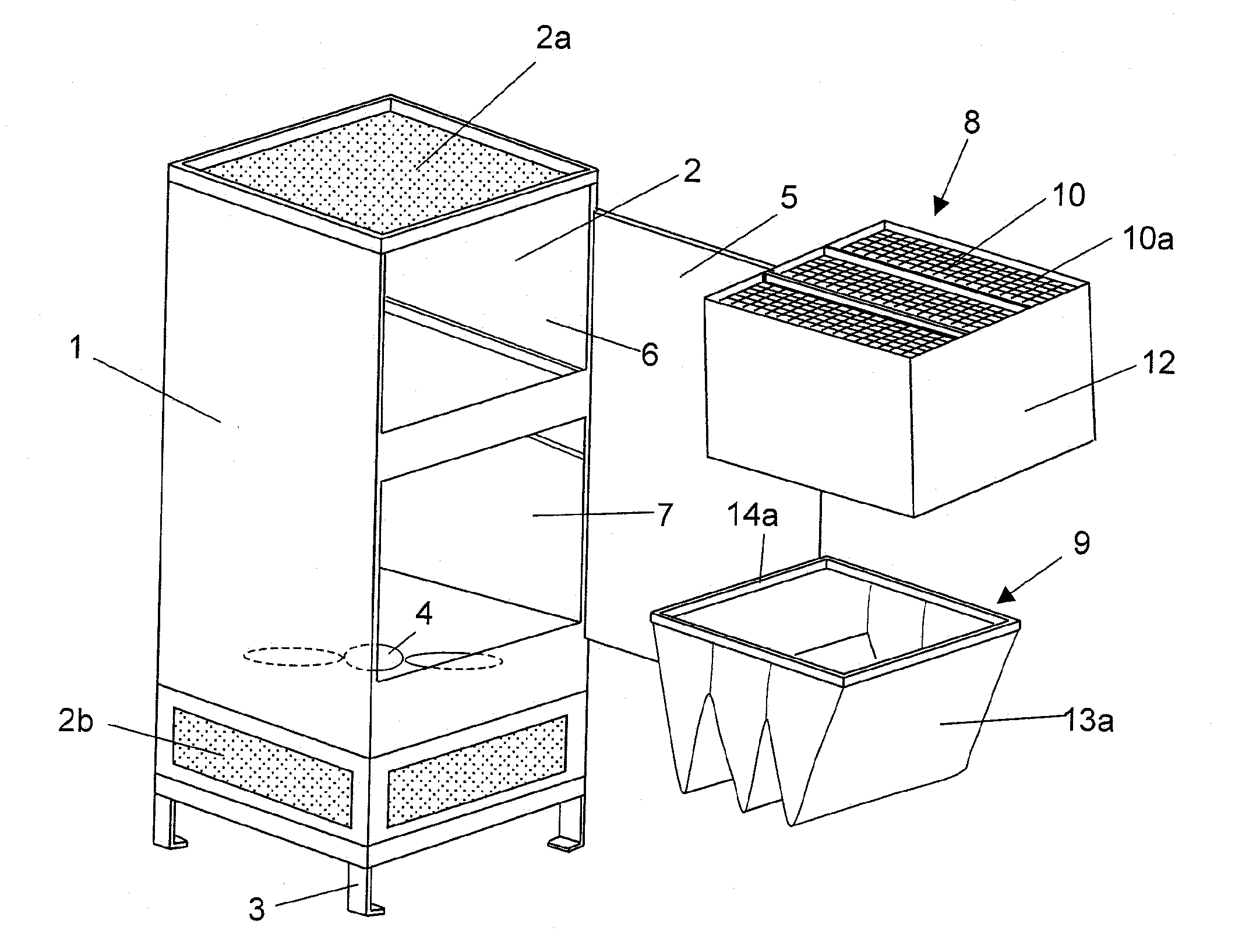
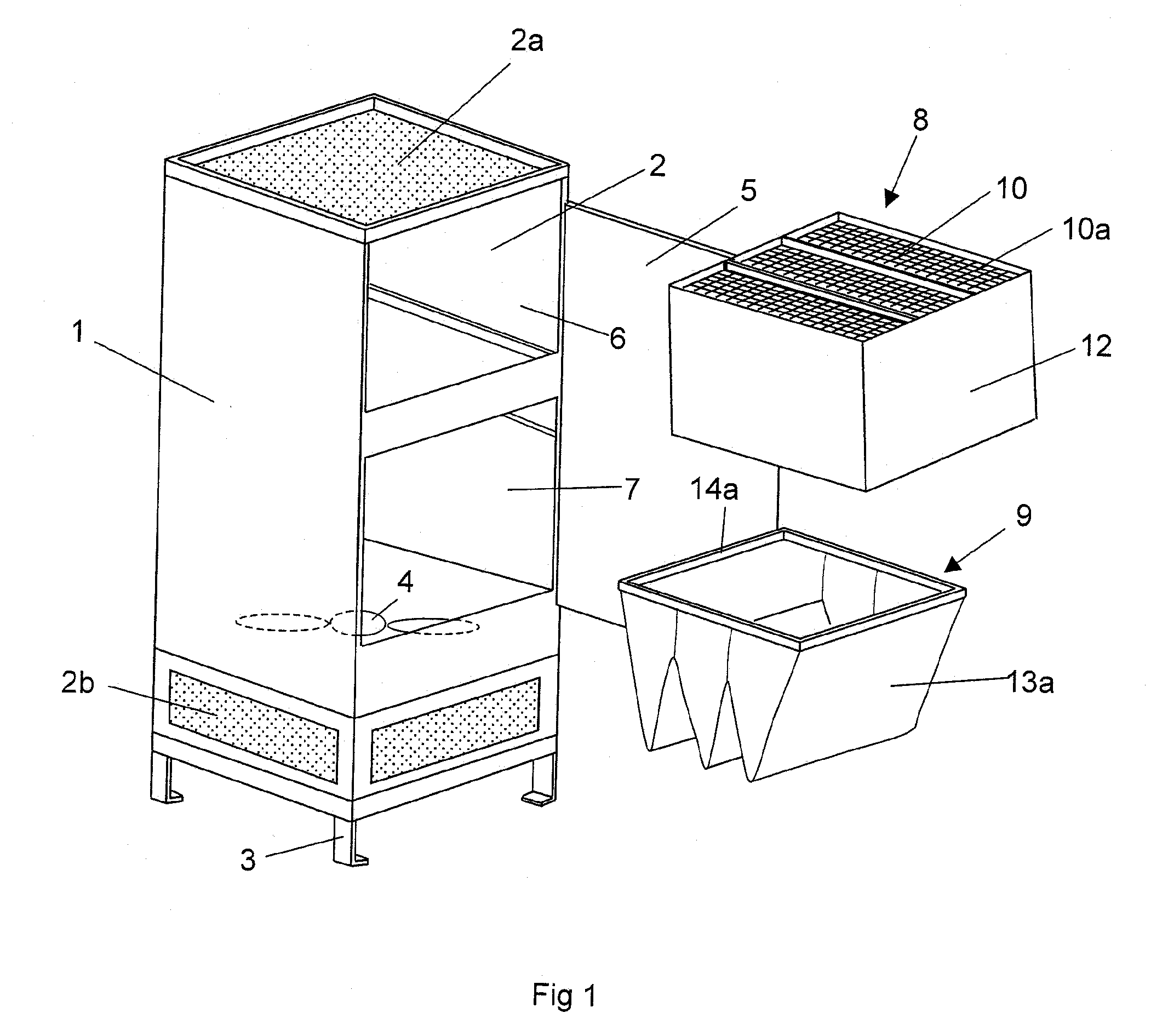
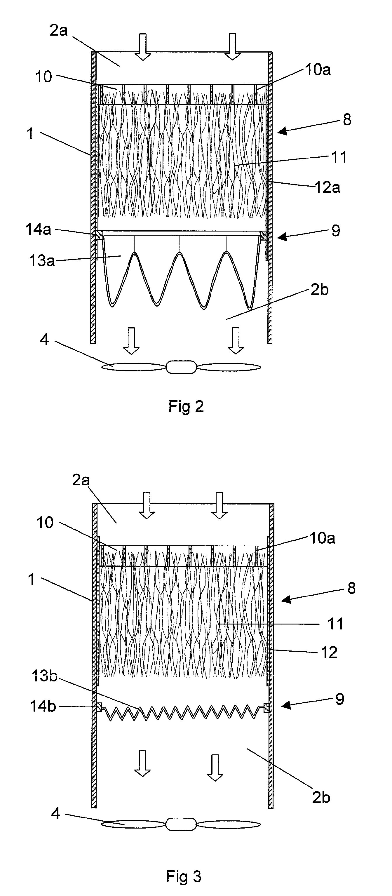
[0018]FIG. 1 shows a filter arrangement performed with wall elements 1 defining an inner air channel 2. In this case, the filter arrangement is provided with legs 3 such that it is placeable on a floor surface. Alternatively, it could be arranged in an elevated position and attached against a wall surface, roof surface or the like. The air channel 2 has an axial inlet opening 2a for air which is located at an upper end of the filter arrangement and radial outlet openings 2b which are located at a lower end of the filter arrangement. The filter arrangement comprises a homogeneous bottom plate 1a which causes the air to only flow out from the filter arrangement through the radial outlet openings 2b. A fan 4 is adapted to accomplish a forced air flow through the air channel 2. The filter arrangement comprises an openable cover 5, which in a closed position, seals a first opening 6 and a second opening 7 to the air channel 2. When the cover 5 is in an open position, it is possible to mo...


PUM

PropertyMeasurementUnit
distanceaaaaaaaaaa
electrostatic chargeaaaaaaaaaa
pressure dropaaaaaaaaaa

Abstract

An air filter arrangement comprises an air channel, a first air filter mounted in the air channel, which first air filter comprises a filter frame provided with at least one passage, and a filter body comprising electrostatically chargeable fibres attached to the filter frame. The filter body extends from the filter frame to a position located at a distance from and downstream the filter frame. The air filter arrangement comprises a second air filter comprising a filter cloth which, in a mounted state, is adapted to extend across the air channel such that it is flown through by air flowing in a substantial longitudinal direction in the air channel, and that the second air filter is mounted in the air channel in a position located downstream the first air filter with respect to the flow direction of the air through the air channel.

Description

FIELD OF THE INVENTION[0001]The present invention relates to an air filter arrangement and a method for manufacturing of such air filter arrangement. The air filter arrangement comprises an air channel, a first air filter which is mounted in the air channel, which first air filter comprises a filter frame provided with at least one passage for through flow of air and a filter body comprising electrostatically chargeable fibres which are attached to the filter frame such that the filter body obtains an extension from the filter frame to a position located at a distance from and downstream the filter frame with respect to the intended flow direction of the air through the air channel.BACKGROUND OF THE INVENTION[0002]When air flows through a first air filter of the above-mentioned kind, mutual motions between the fibres in the filter body are provided such they rub against each other. This rubbing and the friction provided when air flows pass the fibres result the fibres maintaining an...

Claims


Application Information

Patent Timeline
Patent Type & Authority Applications(United States)
IPC IPC(8): B03C3/017B01D50/00B23P11/00
CPCB01D46/0023B01D46/0032B01D2273/30Y10T29/49826B03C3/30B03C3/64B03C3/09B03C3/017B01D46/62B01D50/00
Inventor KRANTZ, STAFFAN
Owner ZEHNDER GROUP NORDIC
Why Eureka
Try Eureka