Dish rack with removable grate

Inactive Publication Date: 2010-03-11
MULAW AZANAW
View PDF22 Cites 29 Cited by
  • Summary
  • Abstract
  • Description
  • Claims
  • Application Information

AI Technical Summary

Benefits of technology

[0010]This invention has advantages in that it takes up a minimum of countertop space; it collects the drip water in an inconspicuous drawer; it is relatively inexpensive when made with a sturdy dishwasher-safe plastic; it can be easily disassembled and the components cleaned in a dishwasher; and it is easily car

Problems solved by technology

Yet none of the prior art describes a compact, solid form dish rack with a flat-panel grate, easily removable utensil cu

Method used


Image

  • Dish rack with removable grate
  • Dish rack with removable grate
  • Dish rack with removable grate

Examples


Embodiment Construction

[0021]In the following description, reference is made to the accompanying drawings, which form a part hereof and which illustrate several embodiments of the present invention. The drawings and the preferred embodiments of the invention are presented with the understanding that the present invention is susceptible of embodiments in many different forms and, therefore, other embodiments may be utilized and structural, and operational changes may be made, without departing from the scope of the present invention.

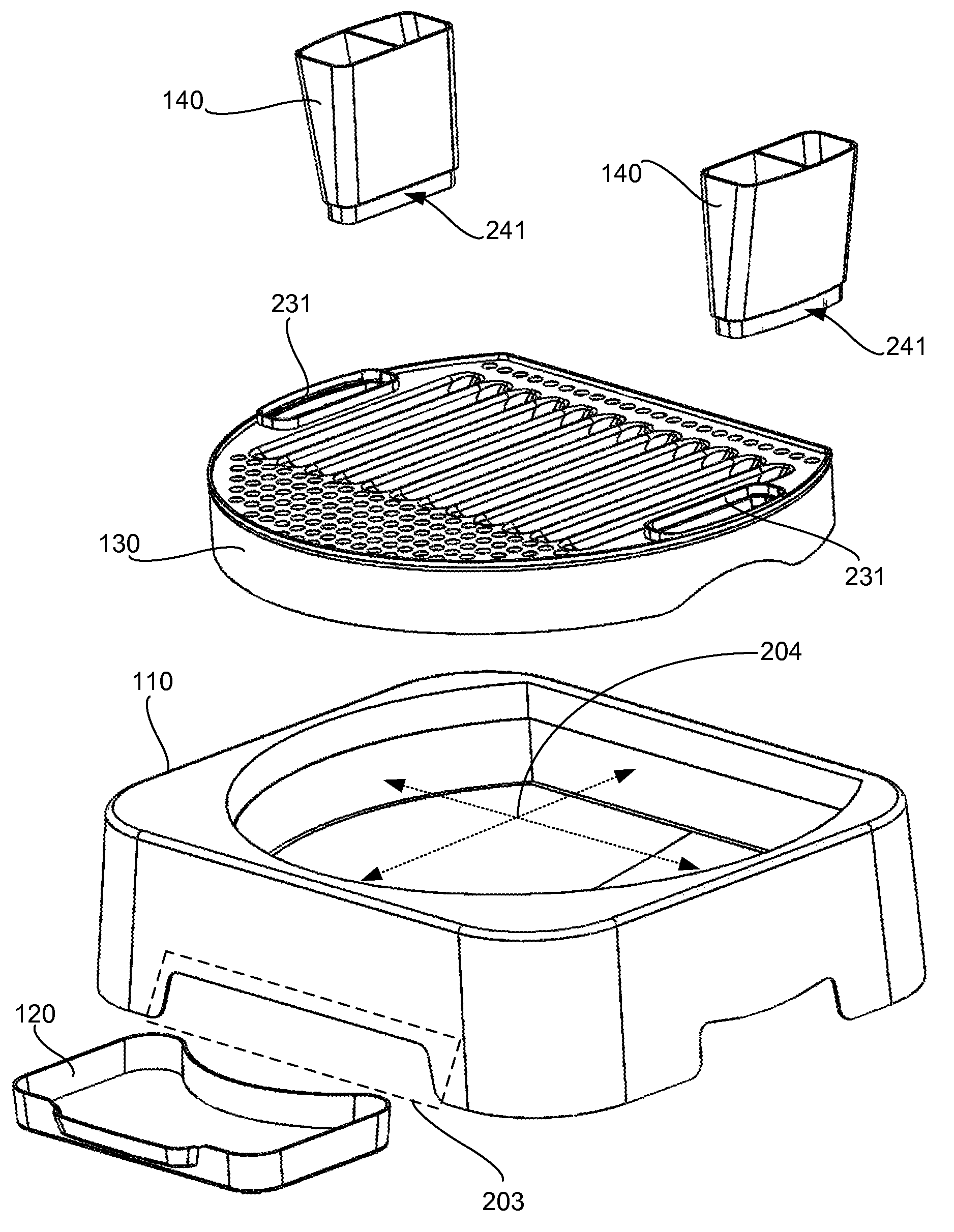
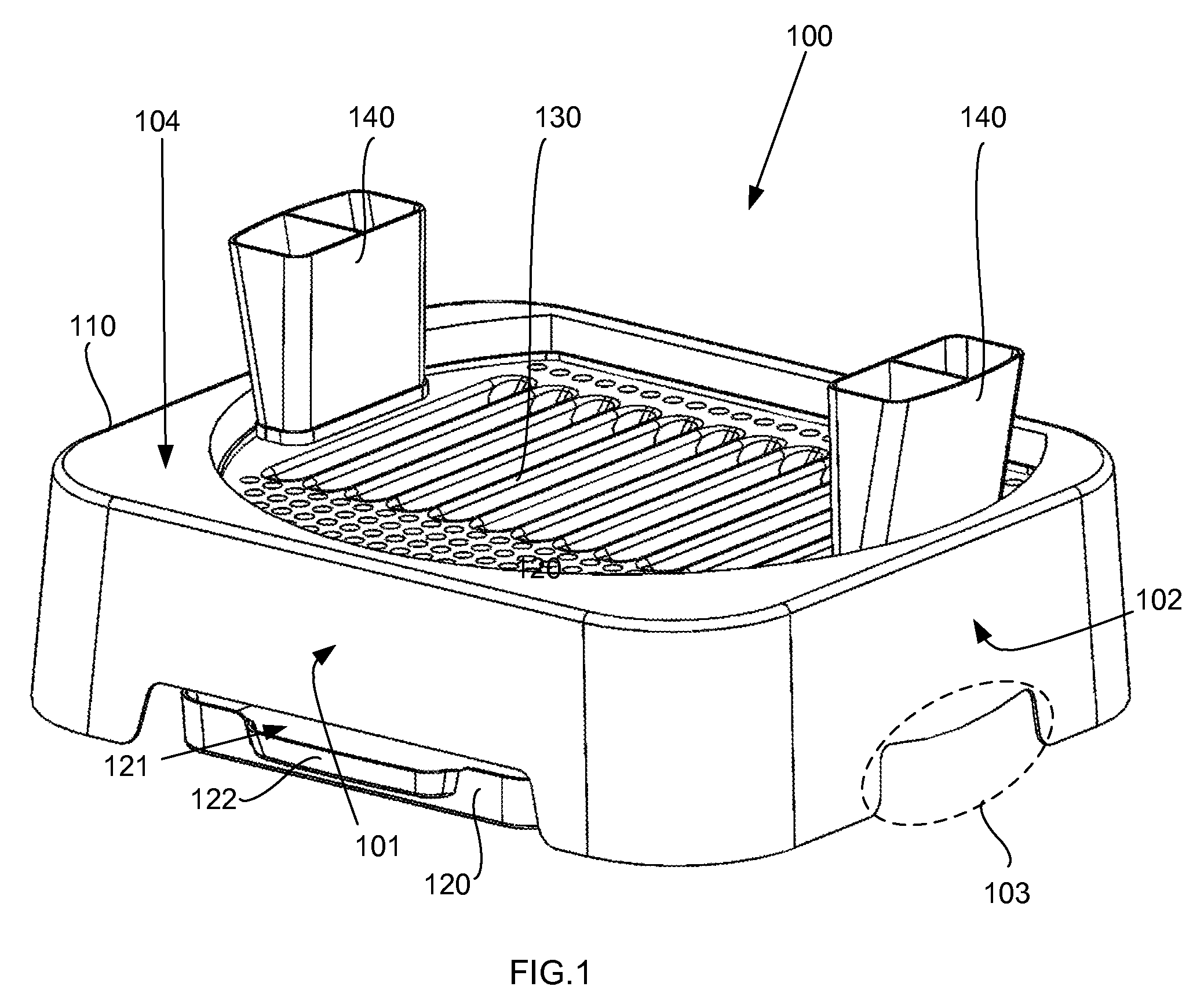
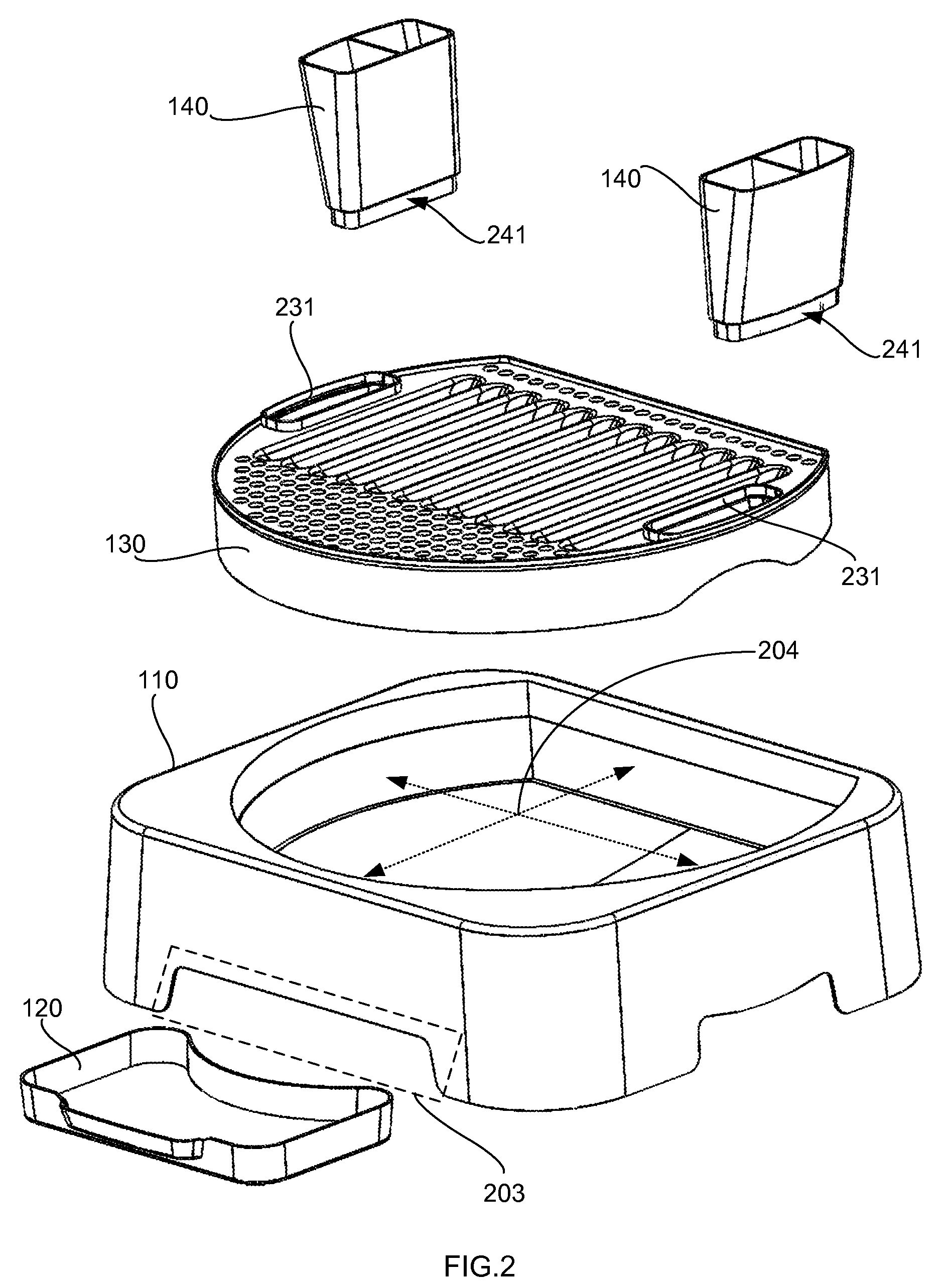
[0022]A preferred embodiment of the invention is shown in perspective in FIG. 1 and in elevation views in FIGS. 3 and 4. It is a countertop dish rack (100) comprising a unitary body (110), a removable drainage tray (120), a flat-panel grate (130), and two or more removable utensil holders (140). An alternative preferred embodiment includes a removable drainage funnel (850), as shown in FIG. 8.

[0023]The preferred embodiment shown in FIG. 1 first comprises a unitary body (110). T...


PUM


Abstract

A countertop dish rack has a compact unitary body holding a flat-panel grate, utensil holders, a funnel and a drainage tray. The unitary body is configured with a portion of approximately planar solid material, such as plastic. A recessed central portion holds the flat-panel grate and drainage funnel both located below the top surface of the unitary body. Hand hold recesses are located on the left side and right side of the unitary body. The funnel discharges water to a removable drainage tray. The utensil holders are removable and are supported within the flat-panel grate.

Description

CROSS-REFERENCE TO RELATED APPLICATIONS[0001]This application is a continuation-in-part of U.S. patent application Ser. No. 12 / 467,266, filed 16 MAY 2009, which in turn claims the benefit of U.S. Provisional Application No. 61 / 095,944, filed 10 SEP. 2008. Both of these applications are hereby incorporated by reference herein.TECHNICAL FIELD[0002]In the field of support racks, a device to support a culinary plate during drying subsequent to washing.BACKGROUND ART[0003]Wire rack dish racks for use on a countertop are widely known and these serve to present a wire frame structure that does not retain drip water. For example, a recent example is United States Patent Application 20090211994, which describes a wire rack and extendable drip tray.[0004]Some inventions employ novel water channeling components. For example U.S. Pat. No. 7,325,695 discloses a dish rack with water drainage channel and spout under the wire mesh to direct drip water into a sink.[0005]Other known dish racks employ...

Claims


Application Information

Patent Timeline
IPC IPC(8): A47G19/08
CPCA47L19/04
Inventor MULAW, AZANAW
Owner MULAW AZANAW
Why Eureka
Try Eureka