

Antenna device
a technology of antennas and antenna details, applied in the direction of antennas, leaky waveguide antennas, antenna details, etc., can solve the problem of degrading the performance of the ebg ground plan
- Summary
- Abstract
- Description
- Claims
- Application Information
AI Technical Summary
Problems solved by technology
Method used
Image

Examples
first embodiment
Description of the First Embodiment
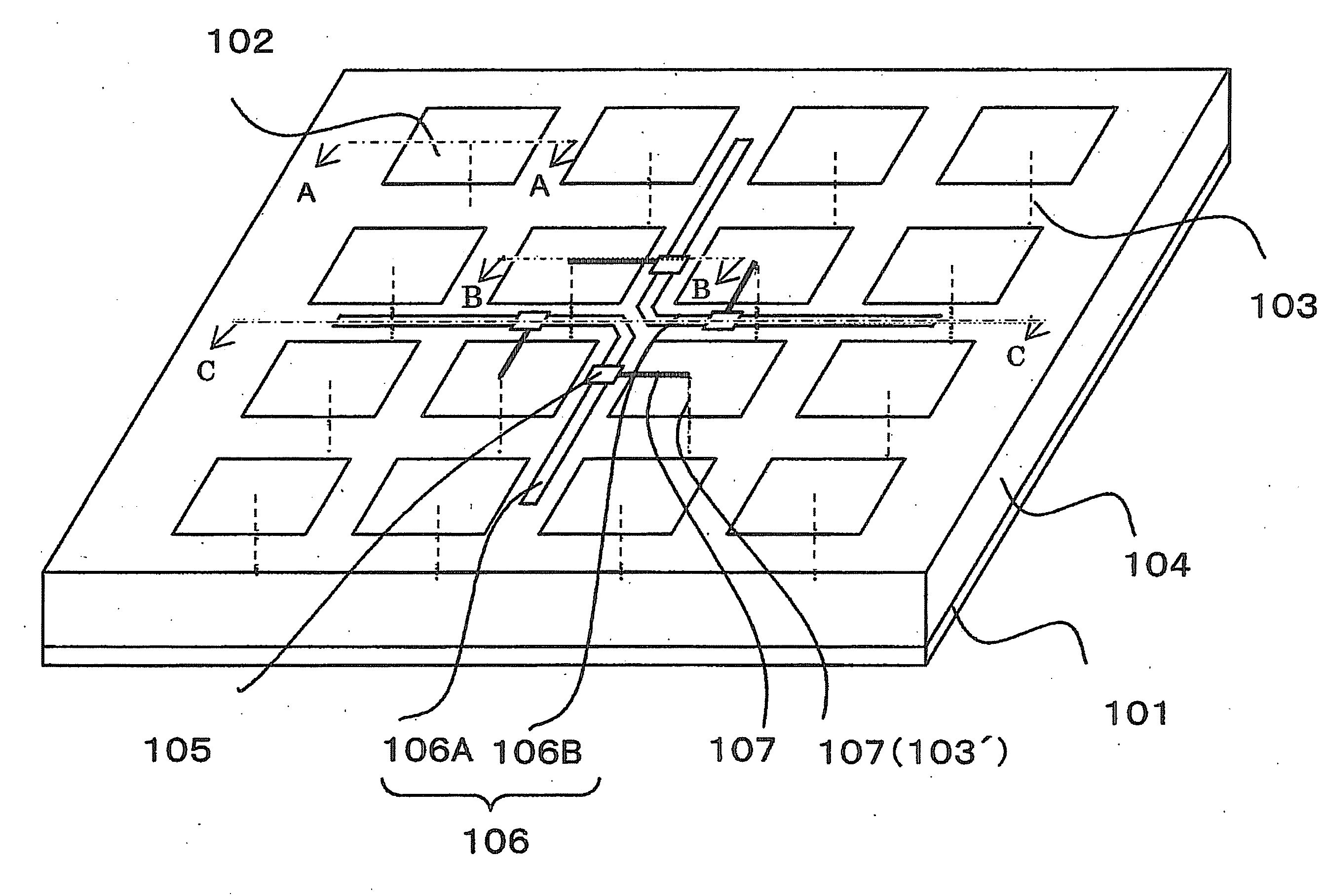
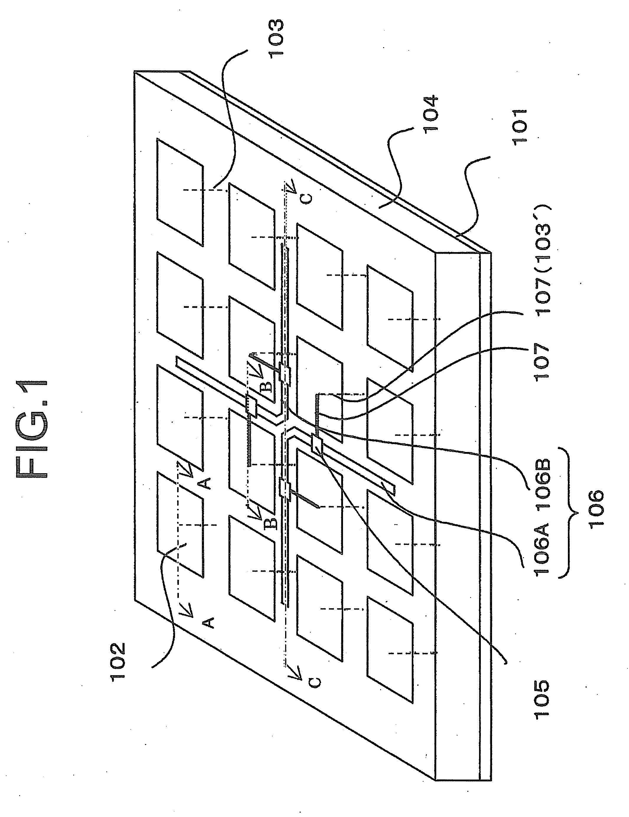
[0024]As shown in FIG. 1, an antenna device includes a reflector plate 101, plane conductors 102, linear conductors 103, a first insulation layer 104, an antenna element 106, a variable impedance element 105 which provides a directional attribute to the antenna element 106, and a control wire 107 which is used for controlling the variable impedance element 105. The reflector plate 101, the plane conductors 102, the linear conductors 103, and the first insulation layer 104 provide the EBG ground plane.
[0025]Moreover, the variable impedance element 105, the antenna element 106, and the control wire 107 provide the tunable antenna. Each plane conductor 102 is set parallel to the reflector plate 101 and connected to the reflector plate 101 through the linear conductor 103. The pairs of the plane conductor 102 and the linear conductor 103 are arranged regularly.
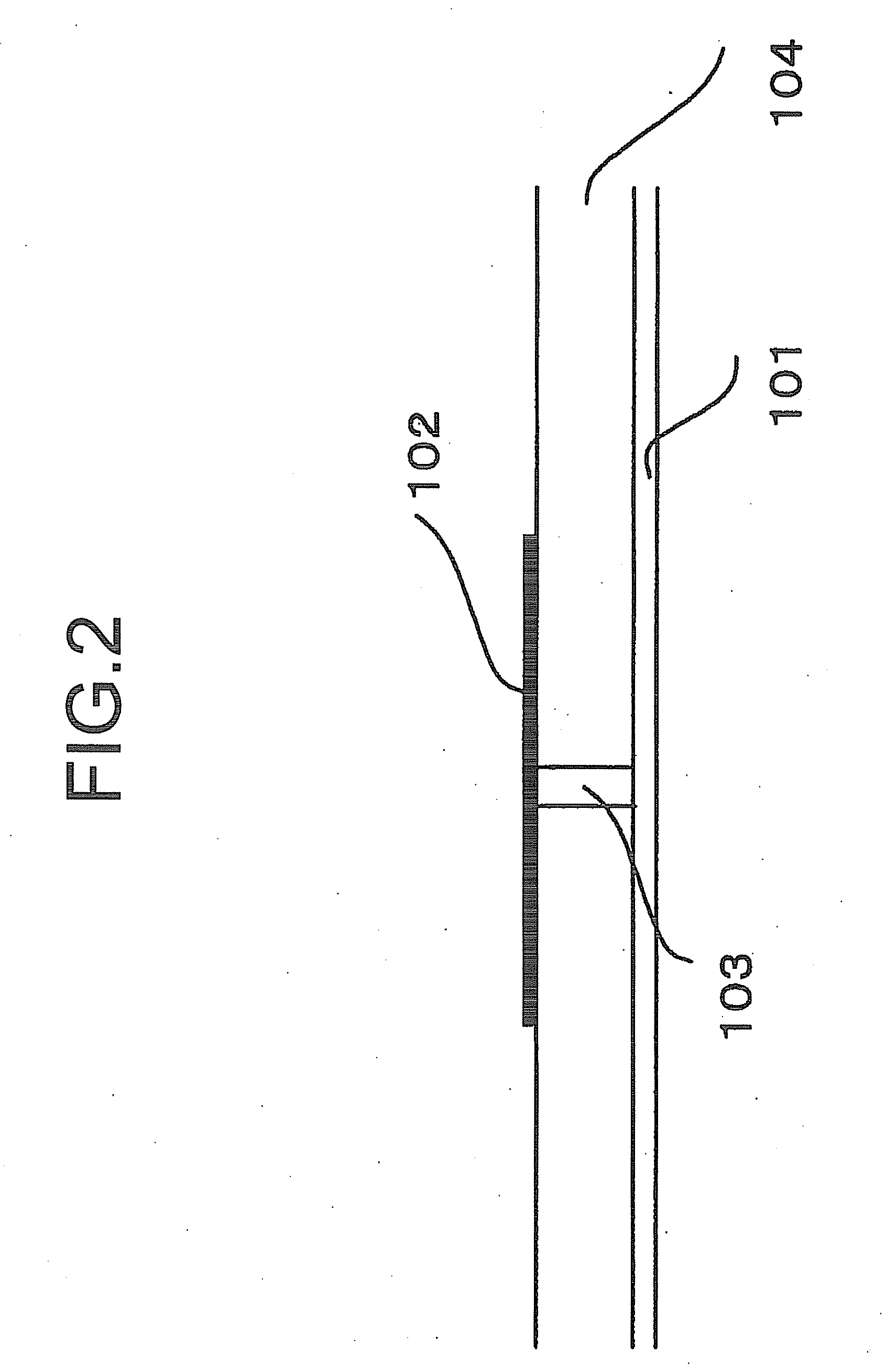
[0026]FIG. 2 is a cross-sectional view of the antenna device along the line A-A in FIG. 1. Th...
second embodiment
Description of the Second Embodiment
[0063]As shown in FIG. 6, the antenna device is almost same as that in the first embodiment, except a tunable antenna. Therefore, we will mainly explain the tunable antenna including an antenna element 206 and a variable impedance element 205 below.
[0064]The antenna element 206 includes sub antenna elements 206A, 206B. In the second embodiment, the shape of the sub antenna elements 206A, 206B is rectangle, and these sub antenna elements 206A, 206B are located along with a line. Each of the sub antenna elements 206A, 206B has a variable impedance element 205 therebetween.
[0065]A direction of a maximum radiation of the antenna element 206 is determined depending on a phase of a high frequency current through the sub antenna elements 206A, 206B. On the other hand, the variable impedance elements 205 can change a phase of the high frequency current, so that the direction of the maximum radiation of the antenna element 206 can be changed.
[0066]Moreover...
third embodiment
Description of the Third Embodiment
[0069]FIG. 7 is a cross-sectional view of the antenna device according to the third embodiment. The antenna device is same as that in the first embodiment, except that a second insulation layer 1101 exists. Therefore, we will mainly explain the second insulation layer 1101 below.
[0070]The first insulation layer 104 is along the reflector plate 101 with no space. The second insulation layer 1101 is set parallel to the reflector plate 101. The antenna element 106 is inserted between the first insulation layer 104 and the second insulation layer 1101 so as to radiate a radio wave to a medium except for air.
[0071]When the medium except for air exist around the antenna element 106 without the second insulation layer 1101, the radio wave from the antenna element 106 is reflected on a surface of the medium and not propagated through the medium. Since the second insulation layer 1101 prevents the radio wave from being reflected by the medium, it lets the r...
PUM
 Abstract
Description
Claims
Application Information