Radio communication method and radio communication terminal

Active Publication Date: 2010-03-11
KYOCERA CORP
View PDF13 Cites 29 Cited by
  • Summary
  • Abstract
  • Description
  • Claims
  • Application Information

AI Technical Summary

Benefits of technology

[0023]According to the characteristics of the present invention, it is possible to provide a radio communication method and a radio communication terminal that can mai

Problems solved by technology

In some cases, however, the transmission power difference cannot be maintained within the predetermined threshold under some communication conditions between a radio communication terminal and a radio base station (Access Network).
In addition, as the radio communication terminal comes closer to the second radio base station, it r

Method used


Image

  • Radio communication method and radio communication terminal
  • Radio communication method and radio communication terminal
  • Radio communication method and radio communication terminal

Examples


first embodiment

Overall Schematic Configuration of Communication System

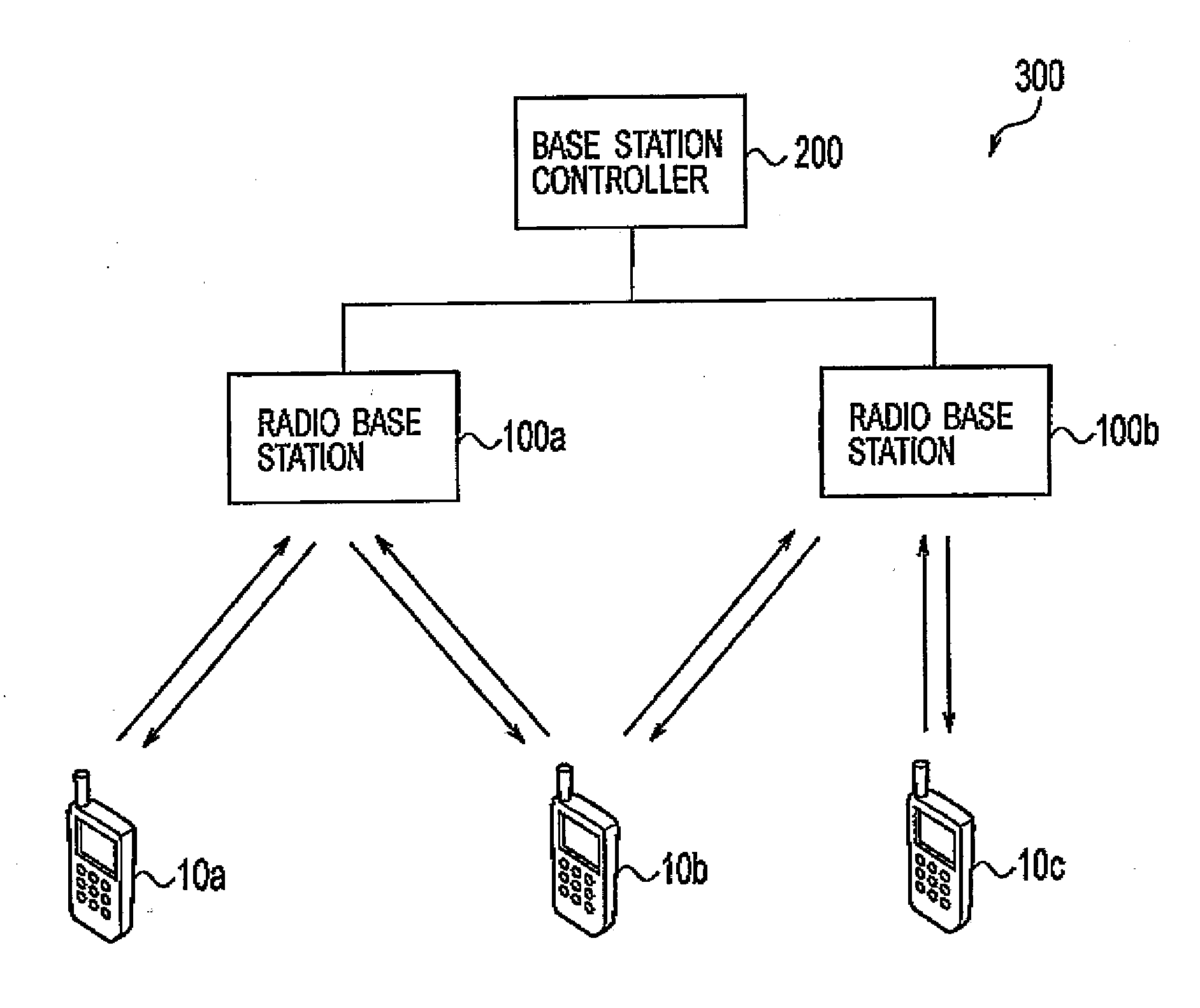
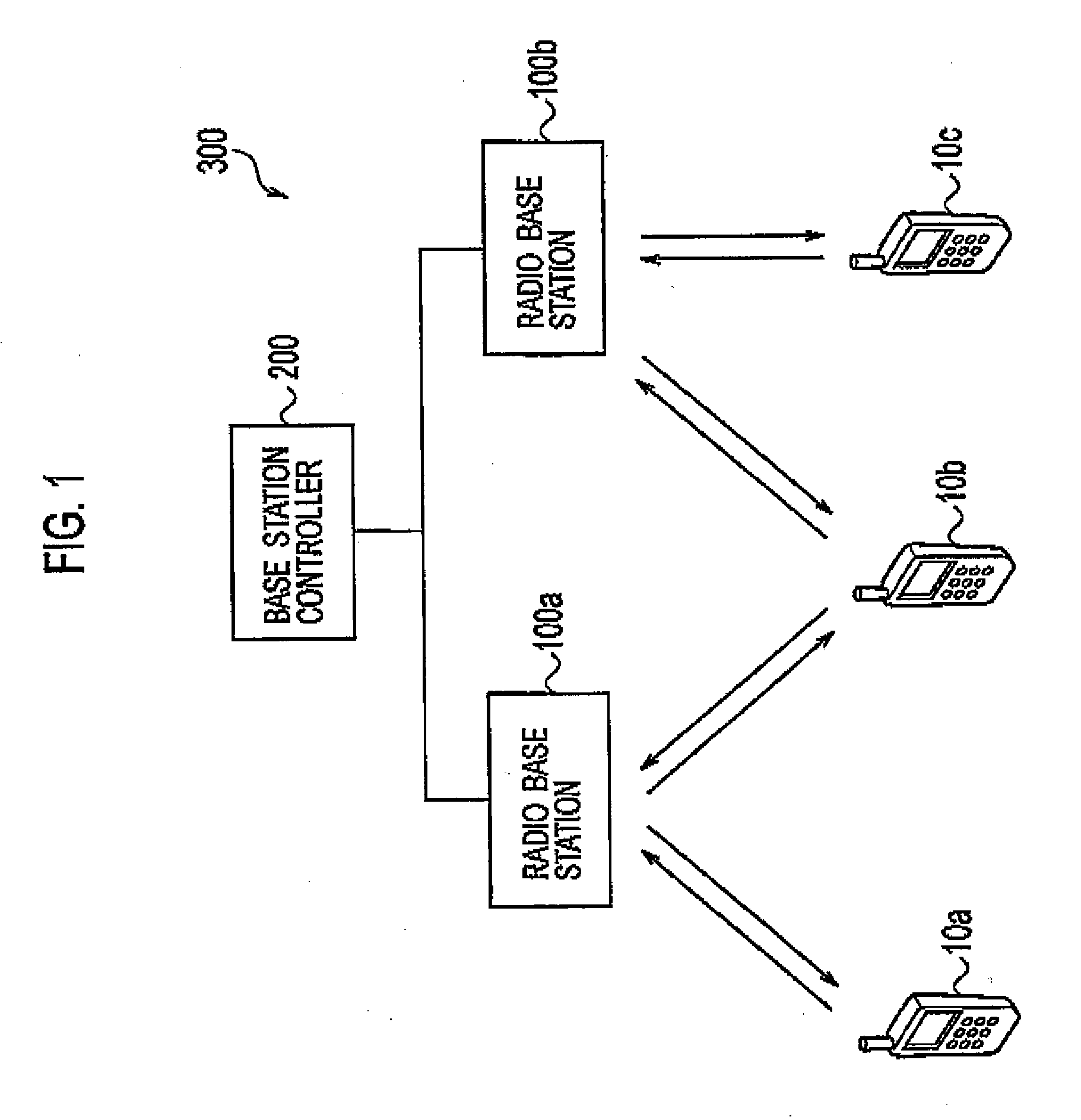
[0042]An overall schematic configuration of a communication is system according to a first embodiment of the present embodiment will be described hereinafter with reference to the drawings. FIG. 1 shows an overall schematic configuration of a communication system 300 according to the first embodiment of the present embodiment.

[0043]As shown in FIG. 1, the communication system 300 includes multiple radio communication terminals 10 (a radio communication terminal 10a to a radio communication terminal 10c), multiple radio base stations 100 (a radio base station 100a and a radio base station 100b), and a base station controller 200.

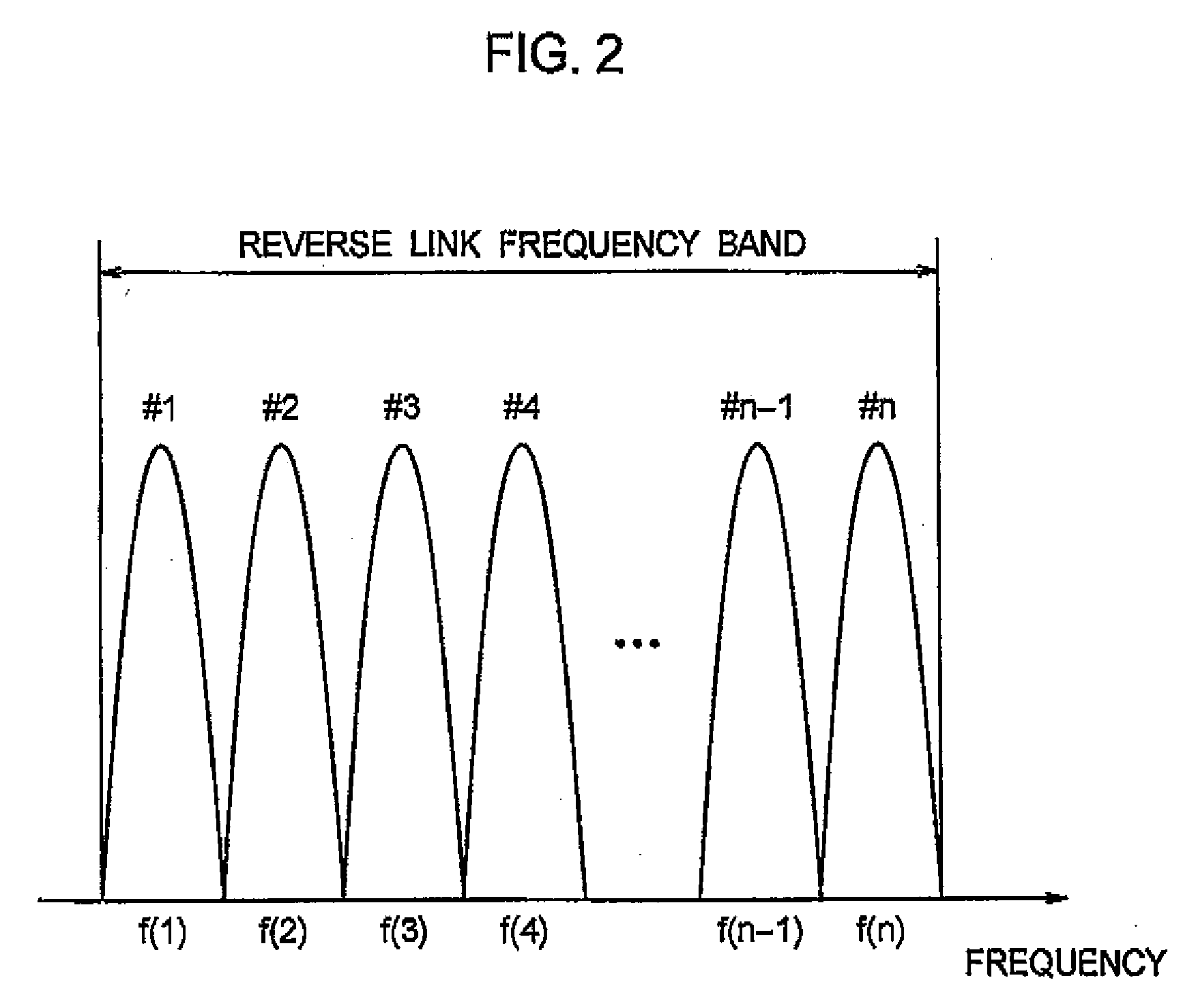
[0044]Each of radio communication terminals 10 transmits reverse link data to each of radio base stations 100 by using a reverse link frequency band assigned for transmitting the reverse link data. Specifically, the reverse link frequency band is divided into multiple carriers. Then, the radio communicati...

second embodiment

[0108]A second embodiment of the present invention will be described hereinafter. In the following, differences between the first embodiment described above and the second embodiment will be mainly described.

[0109]Specifically, in the first embodiment described above, the radio communication terminal 10 change a data rate of reverse link data and an offset value when a transmission power difference between adjacent carriers exceeds a maximum transmission power difference.

[0110]Different from this, in the second embodiment, the radio communication terminal 10 determines whether or not a transmission power difference between adjacent carriers is being expanding, and changes a data rate of reverse link data and an offset value when the transmission power difference between the adjacent carriers has a tendency to expand, and exceeds the maximum transmission power difference.

(Configuration of Radio Communication Terminals)

[0111]A configuration of the radio communication terminals accordi...

third embodiment

[0135]A third embodiment of the present invention will be described hereinafter. In the following, differences between the first embodiment described above and the third embodiment will be mainly described.

[0136]Specifically, in the first embodiment as described above, the radio communication terminal 10 changes a data rate of reverse link data and an offset value when a transmission power difference between adjacent carriers exceeds a maximum transmission power difference.

[0137]In contrast, in the third embodiment, the radio communication terminal 10 changes a date rate of reverse link data and an offset value considering not only a transmission power difference between adjacent carriers but also a difference in data rates between the adjacent carriers.

(One Example of Carrier Control)

[0138]One example of carrier control according to the third embodiment of the present invention will be described hereinafter with reference to the drawings. FIG. 12 to FIG. 15 show an example of carri...


PUM


Abstract

The present invention is summarized as a radio communication method including the steps of calculating a transmission power difference between a transmission power value of a first carrier and a transmission power value of a second carrier; determining whether or not the transmission power difference exceeds a threshold which indicates a maximum transmission power difference allowable between the first carrier and the second carrier; and decreasing a data rate for transmission via one of the first carrier and the second carrier that has the higher transmission power value when the transmission power difference exceeds the maximum transmission power difference.

Description

TECHNICAL FIELD[0001]The present invention relates to a radio communication method in reverse link by multicarrier using multiple carriers, and also to a radio communication method and a radio communication terminal for performing communications by multicarrier.BACKGROUND ART[0002]In recent years, as applications, such as moving images or games, to be handled have been diversified and advanced, the data transmission rate in a mobile communication system has been strongly demanded to be speeded up. With such a background, the Third Generation Partnership Project 2 (3GPP2), for example, defines a scheme for implementing high speed data transmissions by using multiple carriers bundled in a upper layer (so-called multicarrier).[0003]In the case of multicarrier, a radio communication terminal (Access Terminal) generally employs a configuration in which multiple carriers are transmitted by use of a single radio communication circuit, in view of downsizing, reduction in manufacturing cost ...

Claims


Application Information

Patent Timeline
IPC IPC(8): H04L27/00H04W52/04
CPCH04W52/04H04W52/34H04W52/267H04W52/146H04W28/22
Inventor KASHIWASE, SUSUMUMORITA, KUGO
Owner KYOCERA CORP
Why Eureka
Try Eureka