Current canceling variable gain amplifier and transmitter using same

a technology of variable gain amplifier and amplifier, applied in the direction of digital transmission, transmission, volume compression/expansion without controlling loop, etc., can solve the problems of increasing the number of devices needed in the integrated circuit, undesirable increases in power consumption and noise, undesirable nonlinearities of current-to-voltage and voltage-to-current conversion, etc., to eliminate undesirable results and eliminate undesirable results

Active Publication Date: 2010-03-11
TEXAS INSTR INC
View PDF5 Cites 5 Cited by
  • Summary
  • Abstract
  • Description
  • Claims
  • Application Information

AI Technical Summary

Benefits of technology

[0036]It is an object of the present invention to provide a transmitter that eliminates the undesirable results caused by voltage-to-current and current-to-voltage conversions and that also provides a gain curve similar to the one shown in FIG. 4.

Problems solved by technology

Current-to-voltage and voltage-to-current conversions introduce undesirable nonlinearities.
These conversions also cause undesirable increases in power consumption and in noise, and these conversions have the undesirable side effect of increasing the number of devices needed in the integrated circuit.
In other technologies, however, a linear to exponential converter similar to 302 cannot be easily implemented.
Because the FETs in CMOS VGA circuit 500 are not ideal, their leakage will cause this minimum value to be nonzero and not well-controlled.
As explained above, voltage-to-current and current-to-voltage conversions in transmitter 200 cause many undesirable results.
Also as explained above, the conventional gain control method of FIG. 5 does not give the desired gain curve shown in FIG. 4.

Method used


Image

  • Current canceling variable gain amplifier and transmitter using same
  • Current canceling variable gain amplifier and transmitter using same
  • Current canceling variable gain amplifier and transmitter using same

Examples


Embodiment Construction

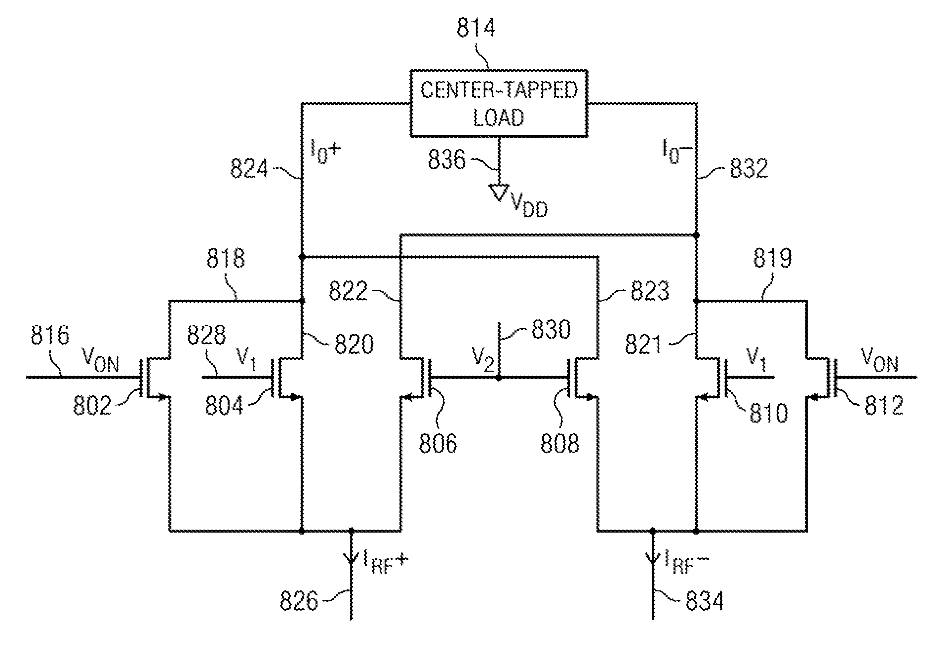
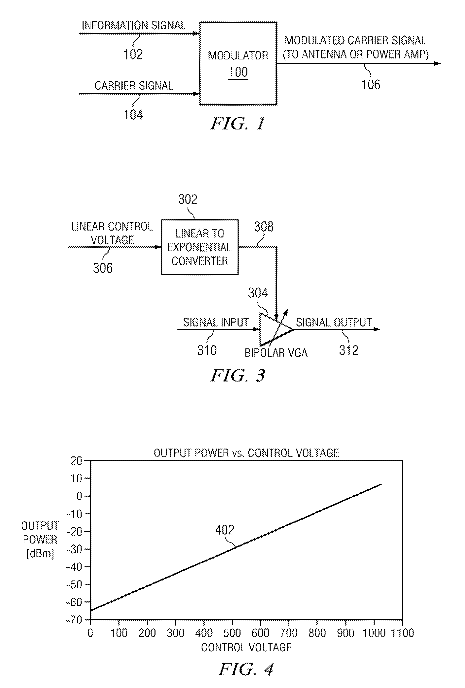
[0050]In accordance with an aspect of the present invention, an example CMOS transmitter eliminates the problems caused by voltage-to-current and current-to-voltage conversions. The example CMOS transmitter also solves the problem of providing a linear relationship between power output in dBm and control voltage when bipolar transistors are not used to provide linear to exponential conversion of the control voltage.

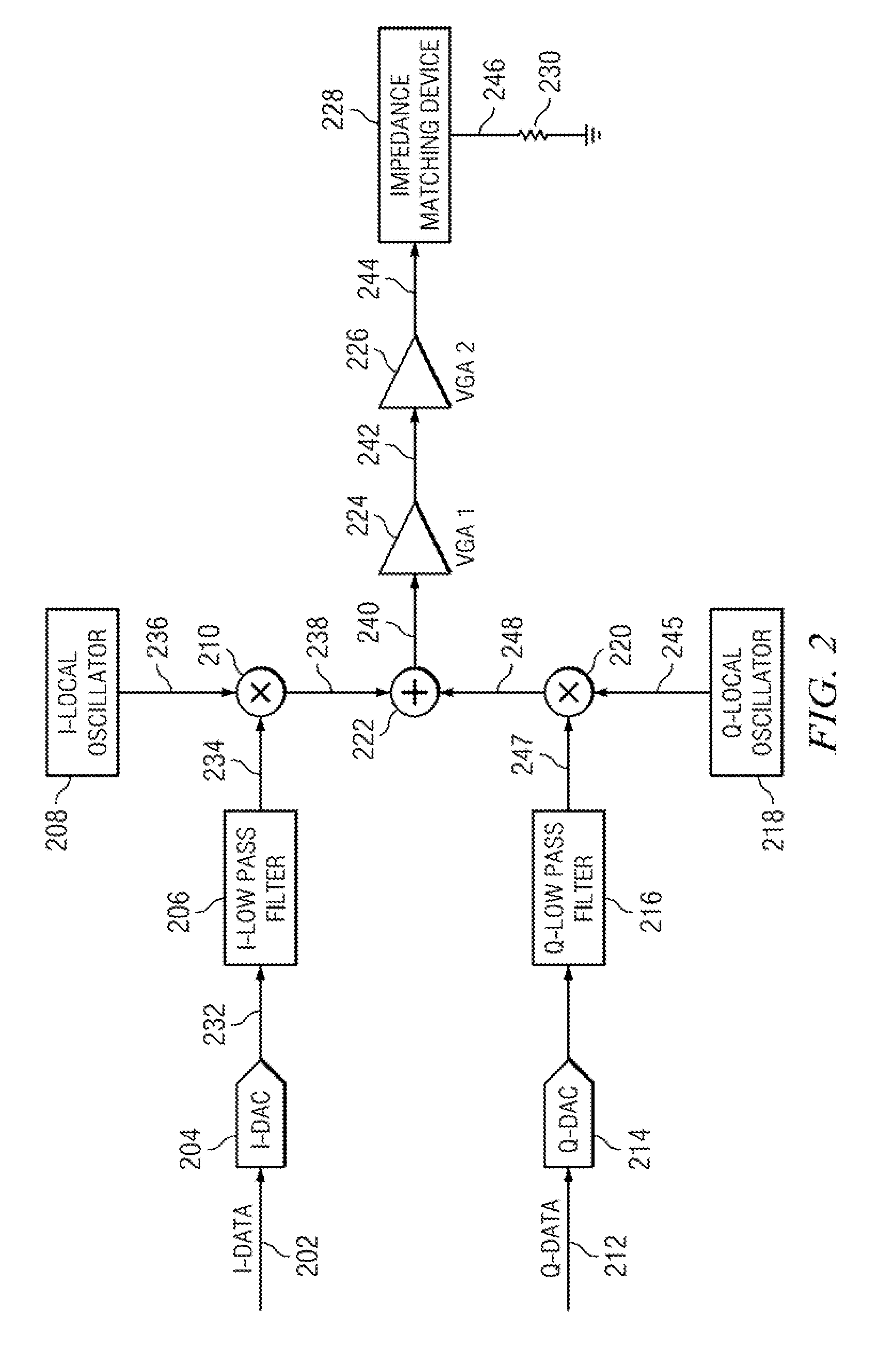
[0051]The example CMOS transmitter avoids the problems caused by voltage-to-current and current-to-voltage conversion because the example CMOS transmitter has no such conversions. In accordance with an aspect of the present invention, all of the circuit portions within the modulator as well as the first amplifier in an example CMOS transmitter accept current as input and provide current as output. Accordingly, in an example CMOS transmitter in accordance with an aspect of the present invention, no voltage-to-current conversions and no current-to-voltage conversions are re...


PUM


Abstract

A current canceling CMOS variable gain amplifier includes a first leg and a second leg. The first leg has a first input line, a first output line, a first ON transistor, a first control transistor and a first subtracting transistor. The second leg has a second input line, a second output line, a second ON transistor, a second control transistor and a second subtracting transistor. The second input line can provide a second input current. The second output line can provide a second output current. The first input line is arranged to provide a first input current to each of the first ON transistor, the first control transistor and the first subtracting transistor. The second input line is arranged to provide a second input current to each of the second ON transistor, the second control transistor and the second subtracting transistor. The first output line is in electrical connection with each of the first ON transistor, the first control transistor and the second subtracting transistor. The second output line is in electrical connection with each of the second ON transistor, the second control transistor and the first subtracting transistor.

Description

[0001]The present application claims benefit under 35 U.S.C. §119 (e) to U.S. provisional patent application 61 / 095,854, filed Sep. 10, 2008, and U.S. provisional patent application 61 / 095,869, filed Sep. 10, 2008, the entire disclosures of which are incorporated herein by reference.BACKGROUND[0002]In the middle of the twentieth century, comic strip detective Dick Tracy was famous for his two-way wrist radio. Comic strip readers probably considered that radio a fanciful invention of science fiction. Today, cellular telephones, wireless Internet connections, keyless automobile control, wireless game controllers, and many other everyday wireless devices have features that Dick Tracy would not have imagined. Today's wireless devices require small, low-cost integrated circuit transmitters, and they often use sophisticated methods of controlling the power output of the transmitter, for extending battery life and for transmitting data. They also need to work across different wireless stan...

Claims


Application Information

Patent Timeline
Patent Type & Authority Applications(United States)
IPC IPC(8): H04L27/00H03F3/45
CPCH03F3/195H04L27/362H03F3/45179H03F2200/18H03F2200/336H03F2200/387H03F2200/451H03F2200/537H03F2200/541H03F2200/72H03F2203/45154H03F2203/45304H03F2203/45311H03G1/0029H03G7/001H03F3/245
Inventor LITMANEN, PETTERI MATTIAKHTAR, SIRAJ
Owner TEXAS INSTR INC
Why Eureka
Try Eureka