Cotyle comprising a sterile interface

a cotyle and interface technology, applied in the field of prosthetic cotyles, can solve the problems of instability of the joint risk of luxation, etc., and achieve the effects of convenient sterilization, simple, reliable and inexpensiv

Active Publication Date: 2010-03-11
GRADEL SA
View PDF9 Cites 16 Cited by
  • Summary
  • Abstract
  • Description
  • Claims
  • Application Information

AI Technical Summary

Benefits of technology

[0033]The placement and orientation insert can be of polyethylene, a low-cost material that can easily be sterilized and can be used in the surgical environment.
[0034]The assembly structure can preferably comprise a threaded fixing hole formed in the placement and orientation insert, enabling the screwing in of a corresponding threaded portion of the impacter. This produces a simple, reliable and inexpensive assembly structure allowing the use of known and available impacters.

Problems solved by technology

The main problem when using a hip prosthesis is the risk of luxation, i.e. escape of the spherical femoral head from the joint cavity.
A drawback of this structure is the occurrence of progressive wear of the joint insert, which causes instability of the joint and a risk of luxation after a few years of use.
The cotyle cavity of a patient has fixed dimensions, however, which can only be modified with great difficulty (or not at all).
However, a great increase in the risks of rupture of the ceramic insert is then observed, either during the impaction of the cotyle to place it, or even during subsequent use of the prosthesis.

Method used


Image

  • Cotyle comprising a sterile interface
  • Cotyle comprising a sterile interface
  • Cotyle comprising a sterile interface

Examples


Embodiment Construction

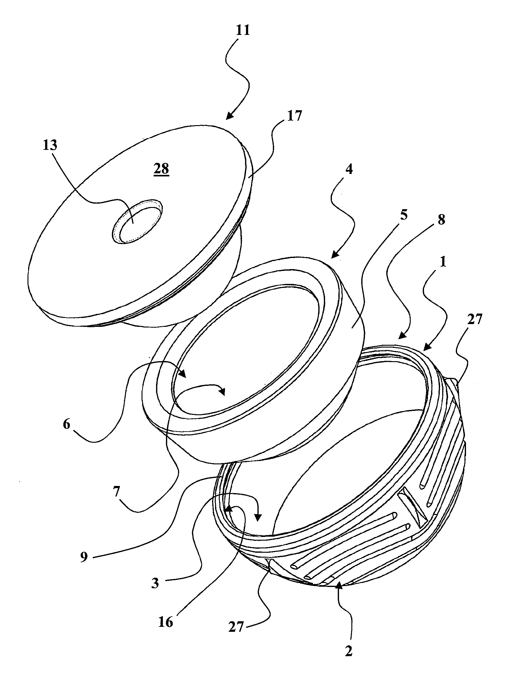
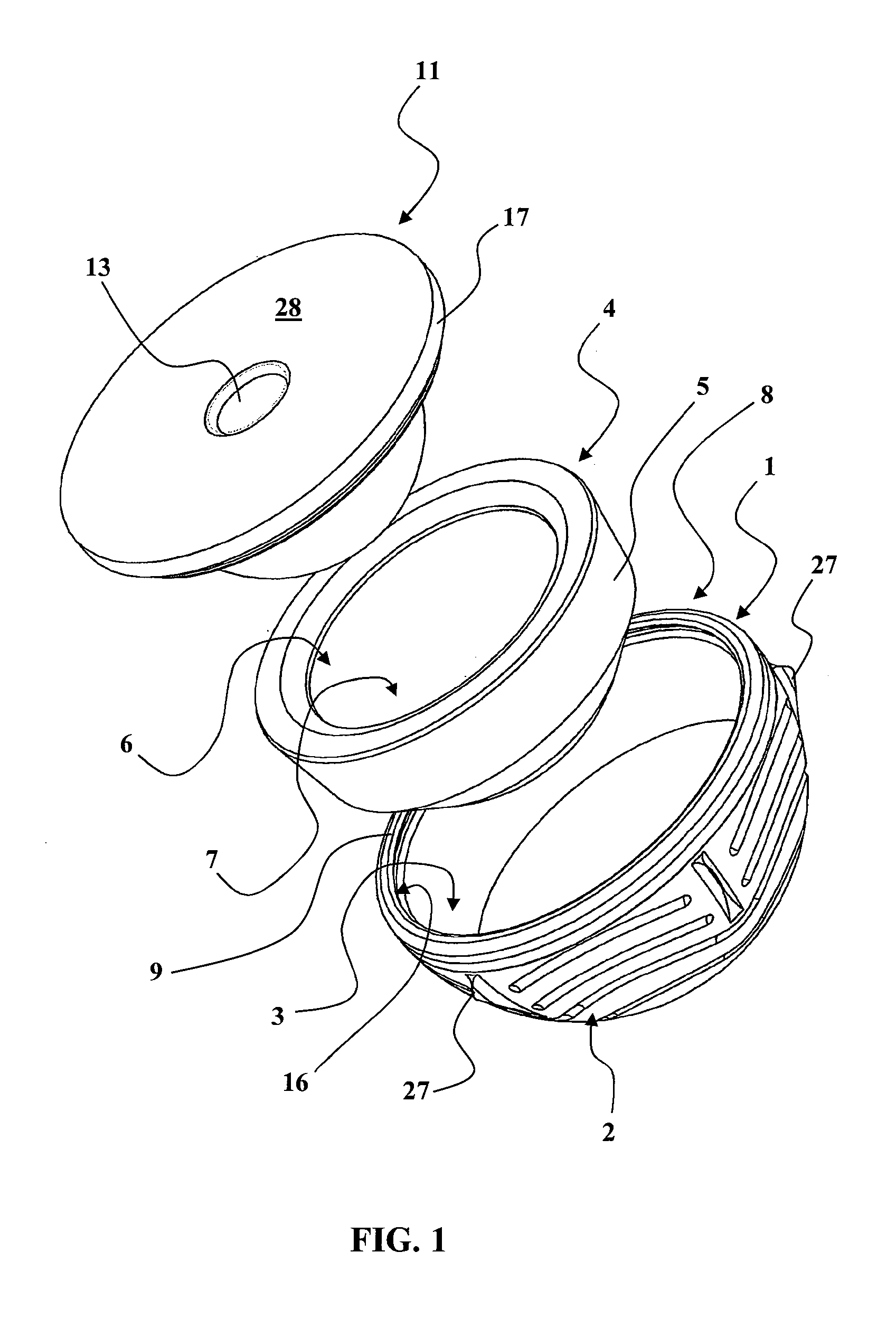
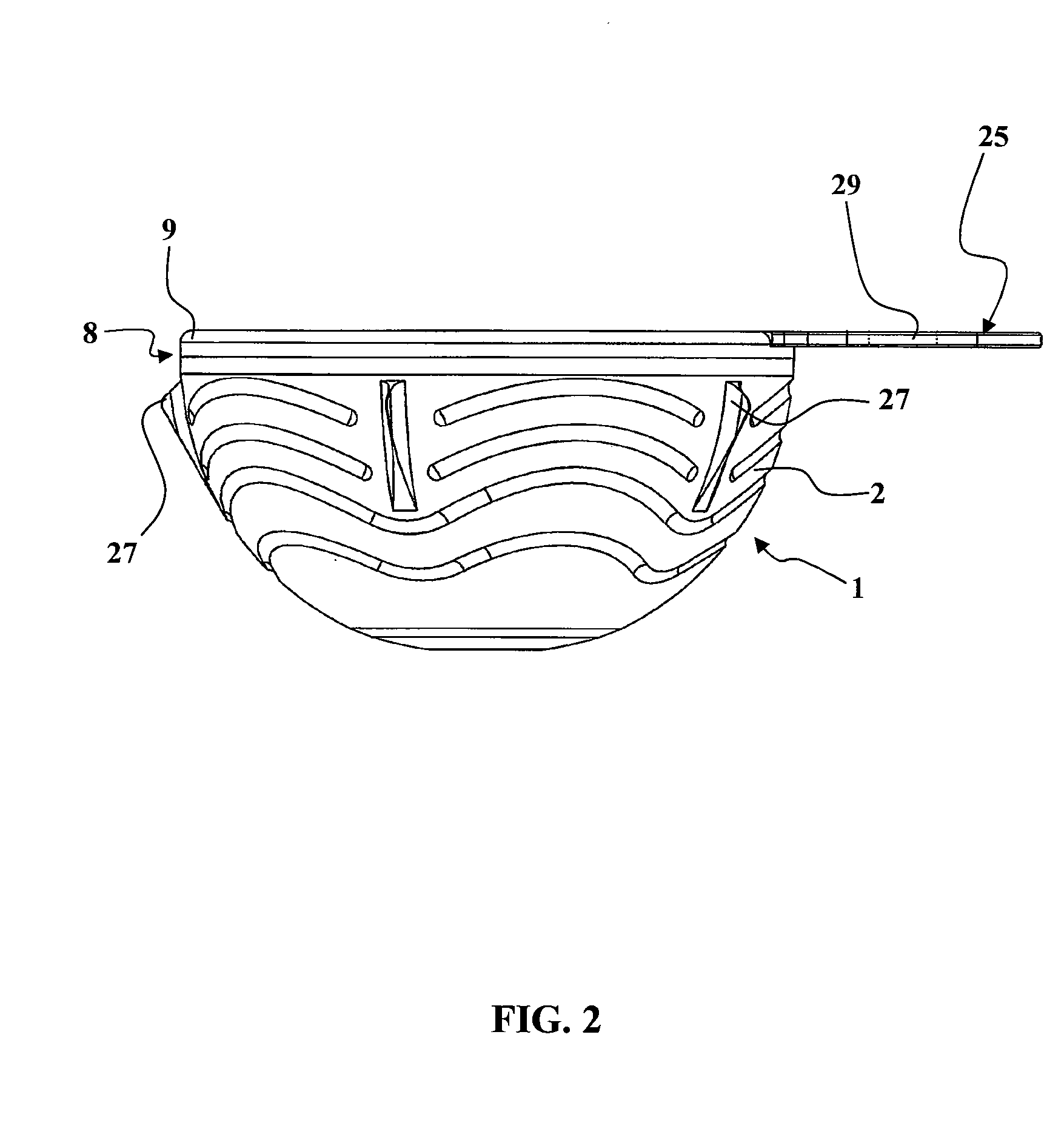
[0070]In FIGS. 1, 3 and 4 there is represented a single-motion or double-motion cotyle. The latter comprises:[0071]an insertion shell 1, having a substantially hemispherical convex exterior anchoring face 2 conformed to be anchored in a cotyle cavity in the pelvis of a patient, and having a concave receiving face 3,[0072]a ceramic fixed final joint insert 4, having an exterior face 5 that engages in the concave receiving face 3 of the insertion shell 1, and having an interior receiving face 6 including a substantially hemispherical concave joint surface 7 to enable engagement and pivoting of a femoral prosthesis head or a mobile joint insert (not represented).

[0073]The final joint insert 4 is called the fixed final joint insert because it is fixed relative to the insertion shell 1.

[0074]In FIGS. 1, 3 and 4, the insertion shell 1 includes anchoring fins 27 intended to penetrate into the bone of the cotyle cavity of the patient to assure good anchoring of the insertion shell 1.

[0075]F...


PUM

PropertyMeasurementUnit
thicknessaaaaaaaaaa
thicknessaaaaaaaaaa
thickaaaaaaaaaa

Abstract

A cotyle including a metallic insertion acetabular shell having an outer, essentially hemispherical, convex anchoring face formed in such a way as to be anchored in a cotyloid cavity of the pelvis of a patient, and a concave receiving face. The cotyle also includes a fixed definitive articular ceramic insert having an outer face engaging in the concave receiving face of the metallic insertion acetabular shell, and an inner receiving face including a concave, essentially hemispherical, articular surface for allowing the engagement and pivoting of a femoral prosthesis head or a mobile articular insert. The cotyle is packed in its assembled sterile state, with the definitive fixed articular ceramic insert engaged in the metallic insertion acetabular shell having a peripheral receiving structure that can receive means for fixing an impacter for positioning a cotyle and is designed in such a way that the impacter can be fixed to the cotyle in the presence of the definitive fixed articular ceramic insert.

Description

TECHNICAL FIELD OF THE INVENTION[0001]The present invention concerns a prosthetic cotyle intended to replace the natural cotyle of the hip.[0002]A total hip prosthesis comprises two parts constituting a ball joint, namely a female part intended to replace the natural cotyle of the hip and a male part intended to replace the head of the femur.[0003]The male part of the joint generally includes a rod, intended to penetrate into the medullary canal of the femur, and the proximal end of which is connected by a neck to a spherical head intended to penetrate into the cotyle.[0004]The female part of the joint, which must replace the natural cotyle of the hip, and that is referred to overall as the cotyle, usually comprises a hemispherical insertion shell, which is accommodated in a prepared cotyle cavity in the bone of the pelvis, and in which is accommodated a final joint insert. The insertion shell is routinely of metal.[0005]The joint insert is made of a material with a low coefficient ...

Claims


Application Information

Patent Timeline
Patent Type & Authority Applications(United States)
IPC IPC(8): A61F2/30A61B17/58B23P11/00
CPCA61B17/86Y10T29/4984A61F2/34A61F2/4609A61F2002/30136A61F2002/30345A61F2002/30578A61F2002/30822A61F2002/30827A61F2002/3208A61F2002/3233A61F2002/3417A61F2002/3419A61F2002/4624A61F2002/4629A61F2002/4631A61F2002/4641A61F2002/4681A61F2002/4693A61F2220/0033A61F2230/0004A61F2310/00011A61F2310/00017A61F2310/00023A61F2310/00179A61F2002/30406A61F2002/3438Y10T29/49826A61F2/32A61F2/4603A61F2/46A61F2002/305A61F2002/30593
Inventor GRADEL
Owner GRADEL SA
Why Eureka
Try Eureka