Double-cone synchronizer for vehicle transmissions

a synchronizer and transmission technology, applied in the direction of interengaging clutches, clutches, friction clutches, etc., can solve the problems of wear on the surface of the synchronizer and hence the life of the synchronizer, complicated assembly, and large axial overall size, so as to reduce the axial overall size, reduce the cost, and the effect of easy assembly

Inactive Publication Date: 2010-03-18
OERLIKON GRAZIANO
View PDF9 Cites 3 Cited by
  • Summary
  • Abstract
  • Description
  • Claims
  • Application Information

AI Technical Summary

Benefits of technology

[0011]It is therefore an object of the present invention to provide a double-cone synchronizer for vehicle transmissions which has

Problems solved by technology

Since the inner rings and the associated engagement ring gears are not permanently drivingly connected for rotation to each other, sliding speeds occur between the respective contact surfaces during the synchronizing phase, which speeds reach high values in case of synchroni

Method used


Image

  • Double-cone synchronizer for vehicle transmissions
  • Double-cone synchronizer for vehicle transmissions

Examples


Embodiment Construction

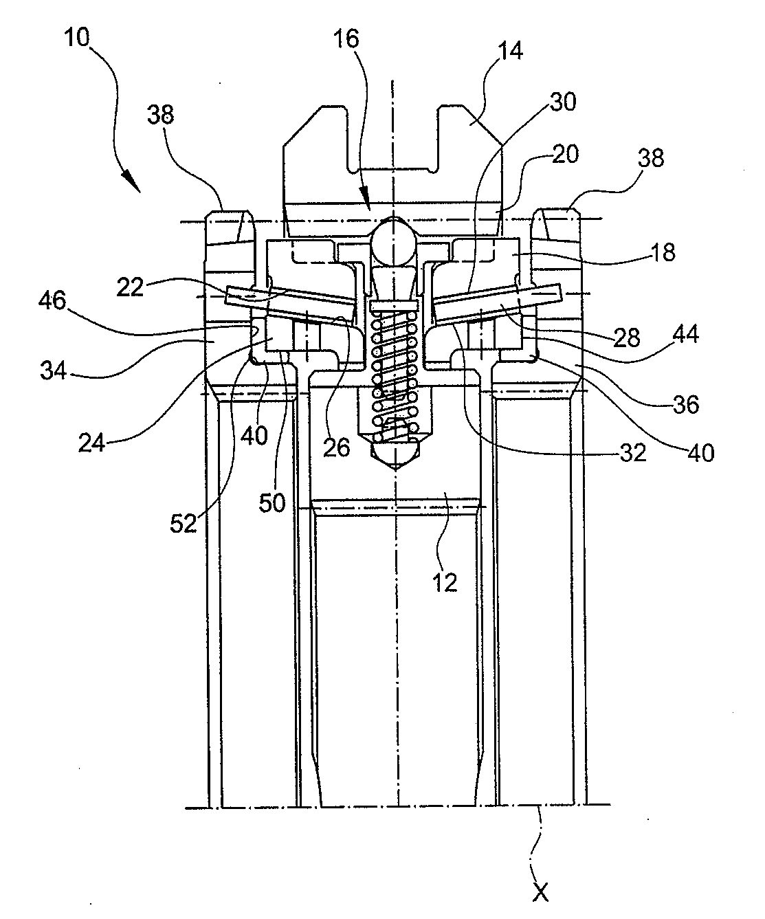
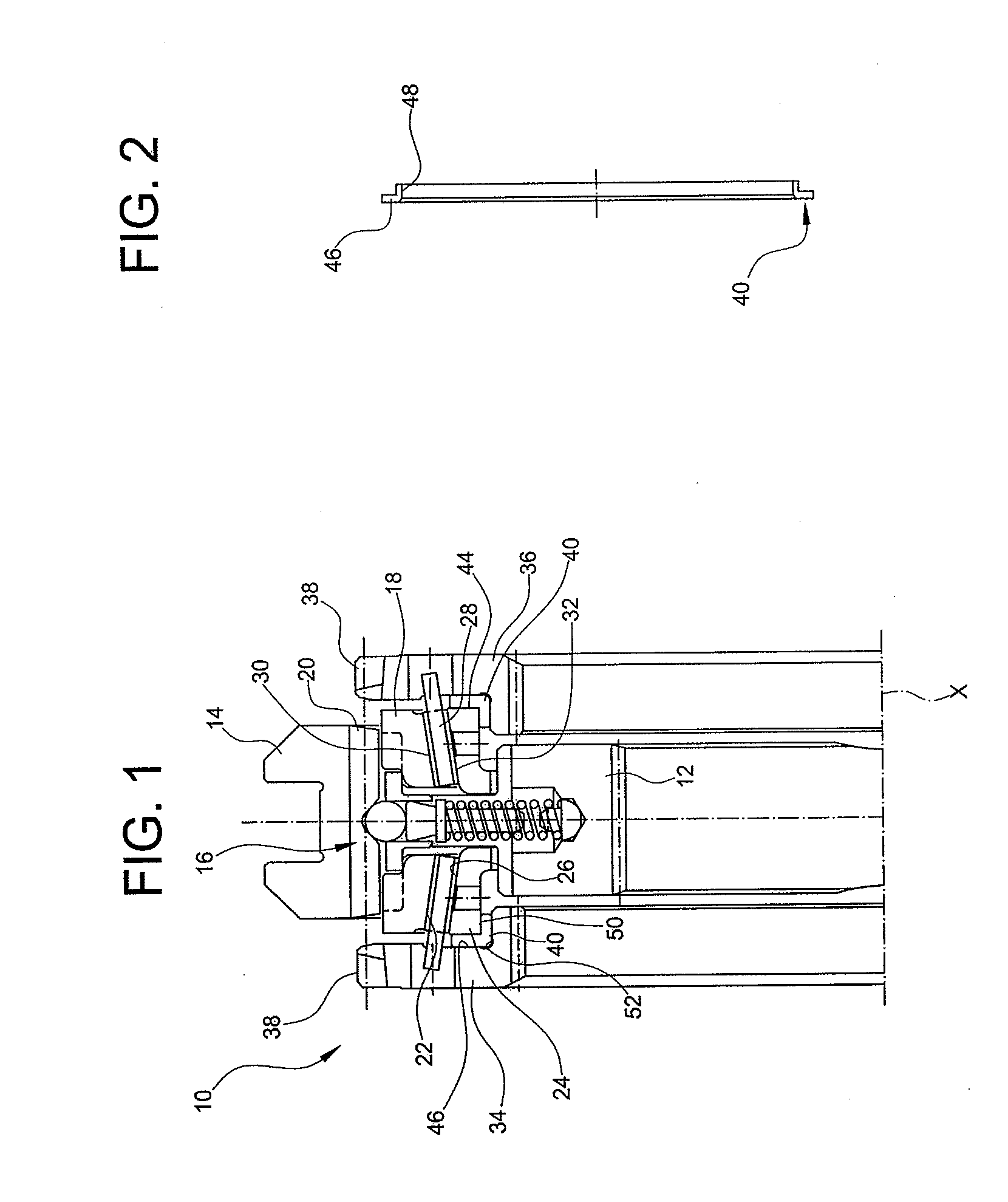
[0016]With reference first to FIG. 1, a double-cone synchronizer for a vehicle transmission is generally indicated 10. The synchronizer 10 basically comprises:

[0017]a hub 12 which in the mounted condition is torsionally coupled to a shaft (not shown) of the transmission, for example by means of a splined coupling;

[0018]an actuating sleeve 14 which is axially (i.e. parallel to the axis of the shaft, indicated X in FIG. 1) slidable under control of a fork-like control member (not shown);

[0019]a pre-synchronizing device which is generally indicated 16 and is radially interposed between the hub 12 and the actuating sleeve 14;

[0020]a pair of synchronizing rings 18 each having an outer engagement toothing (which cannot be seen in FIG. 1 as it is angularly offset relative to the plane of the section) arranged to mesh with a corresponding inner engagement toothing 20 of the actuating sleeve 14 and, on the radially inner side, a conical surface 22;

[0021]a pair of inner rings 24 each having, ...


PUM


Abstract

The synchronizer comprises: a hub, an actuating sleeve, two synchronizing rings each having a conical surface, two inner rings each having a conical surface, two intermediate rings each having a first radially outer conical surface arranged to be brought into contact with the conical surface of the associated synchronizing ring and a second radially inner conical surface arranged to be brought into contact with the conical surface of the associated inner ring, two engagement ring gears intended to be torsionally coupled each to a respective idle gearwheel. According to the invention, the synchronizer further comprises two spacer rings which are each interposed between the respective engagement ring gear and the respective inner ring and each free to rotate relative to these two components so as to prevent the respective opposite axial surfaces from coming into contact with each other.

Description

BACKGROUND OF THE INVENTION[0001]The present invention relates to a double-cone synchronizer for vehicle transmissions, as specified in the preamble of independent claim 1.[0002]A typical double-cone synchronizer for vehicle transmissions, of the type able for example to couple torsionally either one of a pair of idle gearwheels to a transmission shaft, basically comprises:[0003]a hub torsionally coupled to a transmission shaft, for example by means of a splined coupling;[0004]an actuating sleeve which is axially (i.e. parallel to the axis of the shaft) slidable under control of a fork-like operating member;[0005]two synchronizing rings each having an outer engagement toothing arranged to mesh with a corresponding inner engagement toothing of the actuating sleeve and, on the radially inner side, a conical surface;[0006]two inner rings each having, on the radially outer side, a conical surface;[0007]two intermediate rings each having, on the radially outer side, a first conical surfa...

Claims


Application Information

Patent Timeline
IPC IPC(8): F16D23/06
CPCF16D2023/0618F16D23/06
Inventor COLOMBO, SILVANOTURCO, GIORGIO
Owner OERLIKON GRAZIANO
Why Eureka
Try Eureka