Hydrogen and oxygen generator having semi-isolated series cell construction

a technology of hydrogen and oxygen generator and semi-isolated series cell, which is applied in the direction of manufacturing tools, instruments, electric circuits, etc., to achieve the effect of facilitating sealing of the upper edges, minimizing current leakage, and facilitating electrical connections the most easily mad

Inactive Publication Date: 2010-03-18
RICHARDSON DAVID THOMAS
View PDF24 Cites 27 Cited by
  • Summary
  • Abstract
  • Description
  • Claims
  • Application Information

AI Technical Summary

Benefits of technology

The invention is a new design for an electrolysis unit that improves its efficiency and reliability. The unit has a case with thermoplastic side walls and a grooved floor panel, and a top panel that is sealed to the side walls. The outermost laminar plates function as the side walls, and the edges of the plates are bonded to the case to create a leakproof enclosure. The top panel has grooves that facilitate sealing the laminar plates. The electrolysis unit can have different numbers of cells and can use different electrical connections depending on the embodiment. The design also includes a dielectric screw and washers to ensure even spacing between the plates, and sealing of the case edges to minimize current leakage. Overall, the new design improves the performance and reliability of the electrolysis unit.

Problems solved by technology

The technical problem of this patent text is to provide a more efficient and cost-effective method for producing a specific type of chemical compound.

Method used


Image

  • Hydrogen and oxygen generator having semi-isolated series cell construction
  • Hydrogen and oxygen generator having semi-isolated series cell construction
  • Hydrogen and oxygen generator having semi-isolated series cell construction

Examples


first embodiment

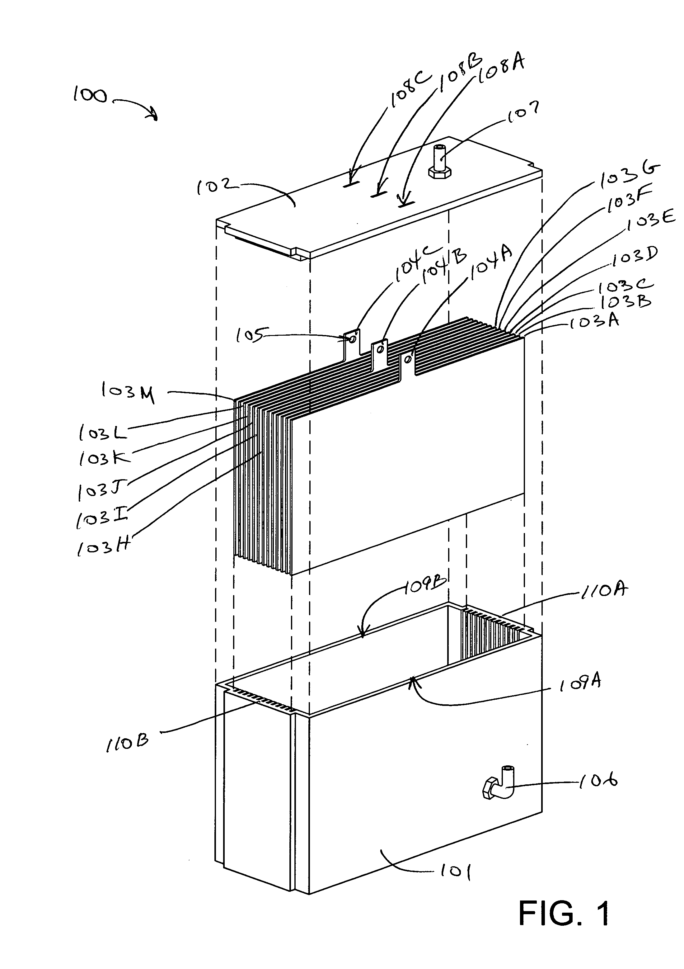
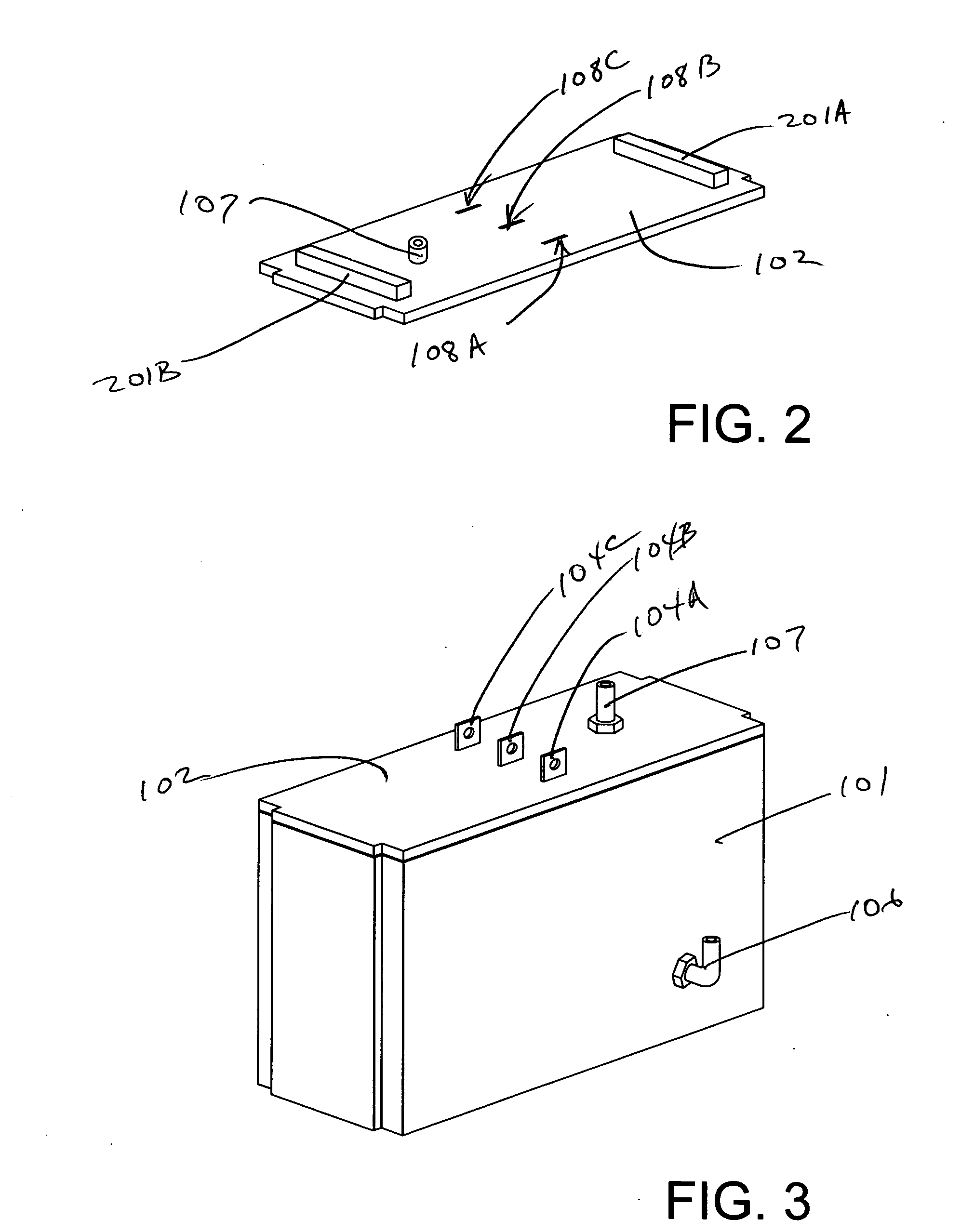
[0032]Referring now to FIG. 1, a first embodiment electrolysis unit 100 includes a case lower portion 101, a case lid 102, thirteen evenly-spaced, parallel laminar plates 103A-103M (103, generally). It will be noted that laminar plates 103A, 103G and 103M each have an electrical connector tab 104A, 104B and 104C, respectively, which extend from an upper central portion thereof. Each of the three connector tabs has an aperture 105 for receiving a threaded fastener that will secure an electrical cable to the connector tab. Laminar plates 103A and 103M will receive a chassis ground connection, while laminar plate 103G will receive a connection to a nominal voltage of 12VDC. It will be noted that the case lower portion 101 is equipped with an electrolyte inlet 106. It will be further noted that the case lid has a gas outlet 107. It will be further noted that the case lid 102 has three rectangular apertures 108A, 108B and 108C, which fit over the three connector tabs 104A, 104B and 104C,...

second embodiment

[0037]Referring now to FIG. 6, the second embodiment electrolysis unit 400 has been assembled, with the fourteen laminar plates 403A-403N seated within their respective plate receiving slots within the case lower portion 401, the case lid 402 secured to the case lower portion 401, and the outermost-laminar plates 403A and 403N seated and sealed within their respective circumferential grooves, which include their case receiving slots in the case lower portion 401 and the grooves in the case lid 402. A waterproof sealant, such as polyurethane adhesive / sealant may be used successfully to seal the case lid 402 to the case lower portion 401 and to seal the outermost laminar plates 403A and 403N within their respective circumferential grooves. As previously indicated, laminar plates 403A and 403N will also be connected to chassis ground through conductors 405A and 405B, respectively. Likewise, connector tabs 404A and 404B are interconnected by a threaded connector stud 601, which is also ...

fourth embodiment

[0042]Referring now to FIG. 11, the fully assembled fourth embodiment electrolyzer unit is shown.


PUM

PropertyMeasurementUnit
Electric potential / voltageaaaaaaaaaa
Levelaaaaaaaaaa
Corrosion resistanceaaaaaaaaaa

Abstract

An electrolysis assembly for providing hydrogen and oxygen gases to the air intake of an internal combustion engine includes an electrolysis unit having a case with at least a pair of opposed, grooved side panels, a grooved floor panel that is unitary with the side panels, and a top panel that is sealed to the side panels. The floor and side panel unit is preferably injection molded from a polymeric engineering thermoplastic. Each groove in the floor panel is aligned with a groove on each side panel, forming a plate receiving slot. Laminar plates made of corrosion resistant metal slip into each slot. When submersed in electrolyte, each pair of adjacent laminar plates forms an electrolytic cell when a voltage differential exists between them. The electrolysis unit incorporates at least one electrolyte supply chamber which maintains electrolyte levels at acceptable levels for an extended period. A hysteresis-type electric float switch constantly monitors the electrolyte level within the electrolyte supply chamber and transfers additional electrolyte to the electrolysis unit from an electrolyte supply tank as needed. Gases produced in the electrolysis unit are bubbled through the electrolyte supply tank before being ducted to the air intake.

Description


Claims


Application Information

Patent Timeline
Owner RICHARDSON DAVID THOMAS
Why Eureka
Try Eureka