
Calibration factor for interferometric optical signal-to-noise ratio measurement

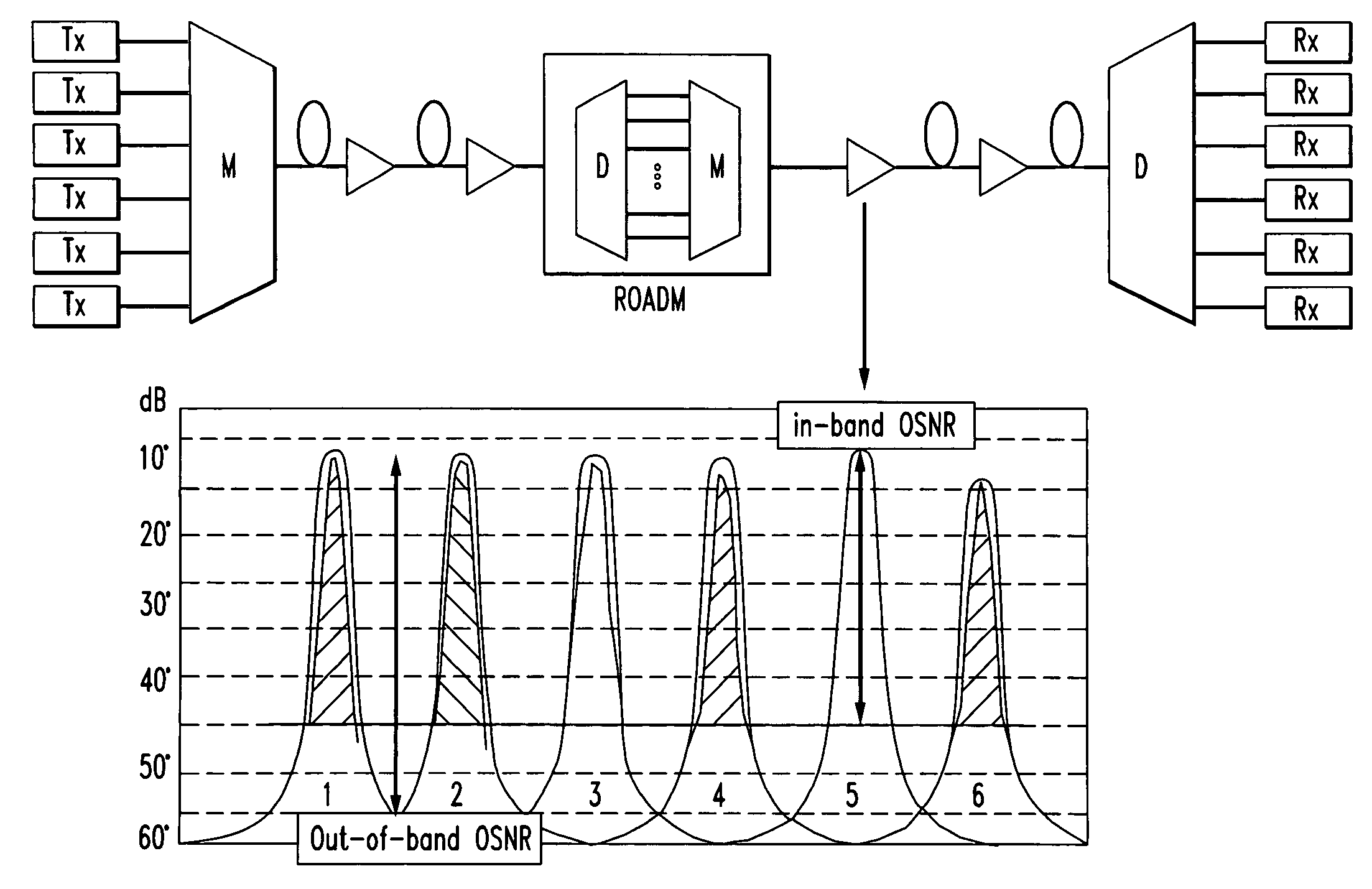
a technology of optical signal and calibration factor, which is applied in the direction of transmission monitoring, transmission monitoring/testing/fault measurement system, electrical equipment, etc., can solve the problems of presenting new measurement challenges for optical monitoring, incorrect osnr value, and variation of noise level of adjacent signal channels

Active Publication Date: 2010-03-18
AT&T INTPROP I L P
View PDF6 Cites 11 Cited by
  • Summary
  • Abstract
  • Description
  • Claims
  • Application Information

AI Technical Summary

Benefits of technology

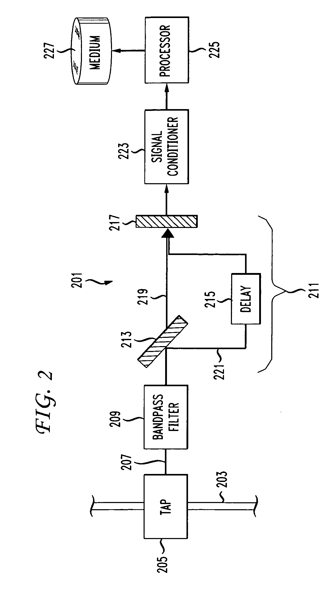
[0011]The inventors have discovered that it would be desirable to have systems and methods that measure the OSNR of a signal channel. Embodiments provide an OSNR measurement that distinguishes the coherent modulated signal power from the incoherent noise power that occupies the same signal channel bandwidth. To determine an accurate OSNR, embodiments derive a calibration factor ζ.

Problems solved by technology

As a result of these different paths, noise levels of adjacent signal channels may vary.
While ROADM-based networks are more economical, they present new measurement challenges for optical monitoring.
Using the linear interpolation method (out-of-band measurement) gives no indication of the noise present at the actual channel wavelength, possibly resulting in an incorrect OSNR value.
This direct spectral measurement using tunable filters cannot distinguish between coherent signal power and incoherent noise power.
In ROADM-based networks, multiple ROADMs are cascaded, leading to a narrowing of the filter shape and making it difficult to detect a hump for accurate noise measurement.
The shoulder method is inaccurate when measuring the in-band noise floor in high-speed ROADM-based networks.
Polarization nulling technique is similarly unreliable, particularly when noise is partially polarized.

Method used


Image

  • Calibration factor for interferometric optical signal-to-noise ratio measurement
  • Calibration factor for interferometric optical signal-to-noise ratio measurement
  • Calibration factor for interferometric optical signal-to-noise ratio measurement

Examples


Embodiment Construction

[0026]Embodiments of the invention will be described with reference to the accompanying drawing figures wherein like numbers represent like elements throughout. Before embodiments of the invention are explained in detail, it is to be understood that the invention is not limited in its application to the details of the examples set forth in the following description or illustrated in the figures. The invention is capable of other embodiments and of being practiced or carried out in a variety of applications and in various ways. Also, it is to be understood that the phraseology and terminology used herein is for the purpose of description and should not be regarded as limiting. The use of “including,”“comprising,” or “having,” and variations thereof herein is meant to encompass the items listed thereafter and equivalents thereof as well as additional items.

[0027]The terms “connected” and “coupled” are used broadly and encompass both direct and indirect connecting, and coupling. Furthe...


PUM


Abstract

Systems and methods are described that measure the OSNR of an optical channel. Embodiments provide OSNR measurement methods that distinguish the intensities of the coherent modulated signal from the incoherent noise intensity occupying the same optical band using a calibration factor ζ.

Description

BACKGROUND OF THE INVENTION[0001]The invention relates generally to measuring the quality of an optical signal transmitted in an optical network. More specifically, the invention relates to systems and methods that measure an optical signal channel's signal-to-noise ratio using an interferometer in conjunction with a derived calibration factor ζ.[0002]In high-speed optical networks based on Reconfigurable Optical Add-Drop Multiplexers (ROADMs) which are used to build dynamically reconfigurable Wavelength Division Multiplexing (WDM) networks, each signal channel may traverse through different routes, optical amplifiers, and add-drop filters. As a result of these different paths, noise levels of adjacent signal channels may vary. Inline optical filters used for demultiplexing the signal channels inside the ROADMs also suppress noise in-between the channels.[0003]While ROADM-based networks are more economical, they present new measurement challenges for optical monitoring. An optical s...

Claims


Application Information

Patent Timeline
Patent Type & Authority Applications(United States)
IPC IPC(8): H04B10/08
CPCH04B10/07953
Inventor BRODSKY, MIKHAILFEUER, MARK DAVIDNELSON, LYNN E.OH, JUNGMI
Owner AT&T INTPROP I L P
Learn More