
Fixing unit and image forming apparatus using same

a technology of fixing unit and fixing belt, which is applied in the direction of electrographic process apparatus, instruments, optics, etc., can solve the problems of defective images, uneven heat distribution between the center portion and the edge portion of the fixing belt, and uneven heat distribution

Active Publication Date: 2010-03-18
RICOH KK
View PDF11 Cites 56 Cited by
  • Summary
  • Abstract
  • Description
  • Claims
  • Application Information

AI Technical Summary

Benefits of technology

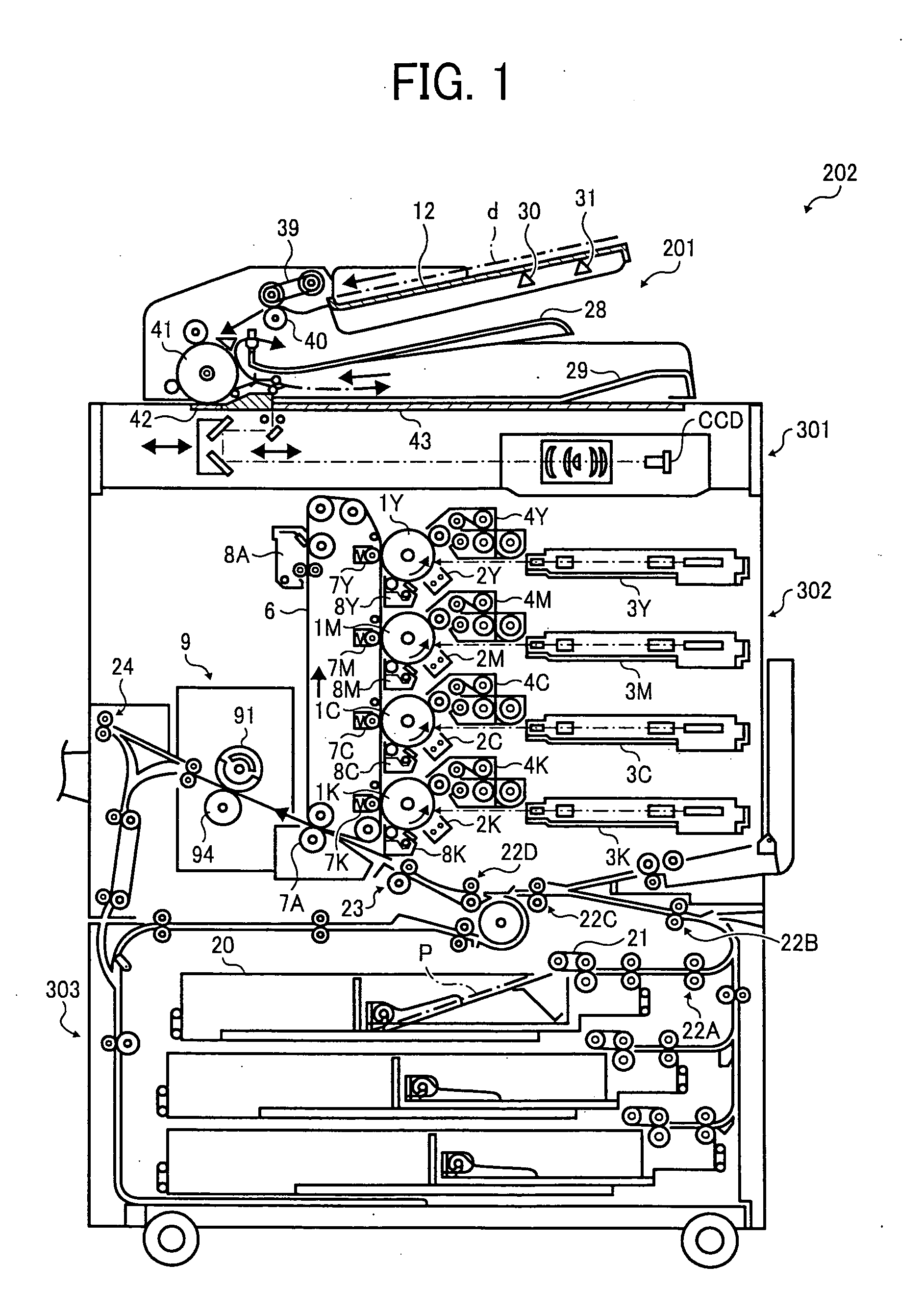
[0005]Typically, image forming apparatuses using electrophotography employ a fixing unit using heat and pressure to fix images on recording media. The fixing unit include a fixing belt having a heat source therein and a pressure roller, with the fixing belt and the pressure roller forming a pressing portion (or nip portion) therebetween. When a transfer sheet having an un-fixed toner image thereon passes the nip portion, the fixing belt and the pressure roller apply heat and pressure to the un-fixed toner image to fix the toner image on the transfer sheet.

Problems solved by technology

However, the fixing belt has a given belt width, and accordingly, continuous image formation on transfer sheets sized narrower than the fixing belt can result in an uneven heat distribution between a center portion and edge portions of the fixing belt.
This uneven heat distribution arises because, in the fixing unit, the fixing belt is heated by the heat source, by which the fixing belt receives heat energy.
Such significant temperature increase at the edge portion of fixing belt may accelerate deterioration of a surface layer of the fixing belt and of the pressure roller, ultimately resulting in defective images.
Further, in such fixing unit, heat energy may not be effectively and efficiently used because heat energy of the heat source is supplied to an area that a transfer sheet is passing (referred to as sheet-pass area), and also supplied to an area that a transfer sheet is not passing through (referred to as sheet-not-pass area).
Accordingly, much of the heat energy of the heat source may be absorbed by the fixed sleeve and the rotatable light-shield member, and thereby heat energy may not be effectively and efficiently used to heat the rotatable sleeve.
Further, because the size of the above-mentioned window in the sheet transport direction is limited, heat energy to heat the rotatable sleeve may need to be increased by using a heat source having a larger heat generating capacity.
However, such larger capacity may unfavorably increase both the size of the fixing unit and an energy consumption level.

Method used


Image

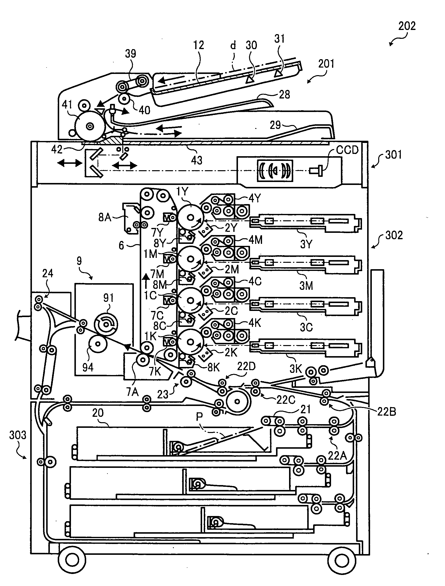
  • Fixing unit and image forming apparatus using same
  • Fixing unit and image forming apparatus using same
  • Fixing unit and image forming apparatus using same

Examples


Embodiment Construction

[0029]A description is now given of exemplary embodiments of the present invention. It should be noted that although such terms as first, second, etc. may be used herein to describe various elements, components, regions, layers and / or sections, it should be understood that such elements, components, regions, layers and / or sections are not limited thereby because such terms are relative, that is, used only to distinguish one element, component, region, layer or section from another region, layer or section. Thus, for example, a first element, component, region, layer or section discussed below could be termed a second element, component, region, layer or section without departing from the teachings of the present invention.

[0030]In addition, it should be noted that the terminology used herein is for the purpose of describing particular embodiments only and is not intended to be limiting of the present invention. Thus, for example, as used herein, the singular forms “a”, “an” and “the...


PUM


Abstract

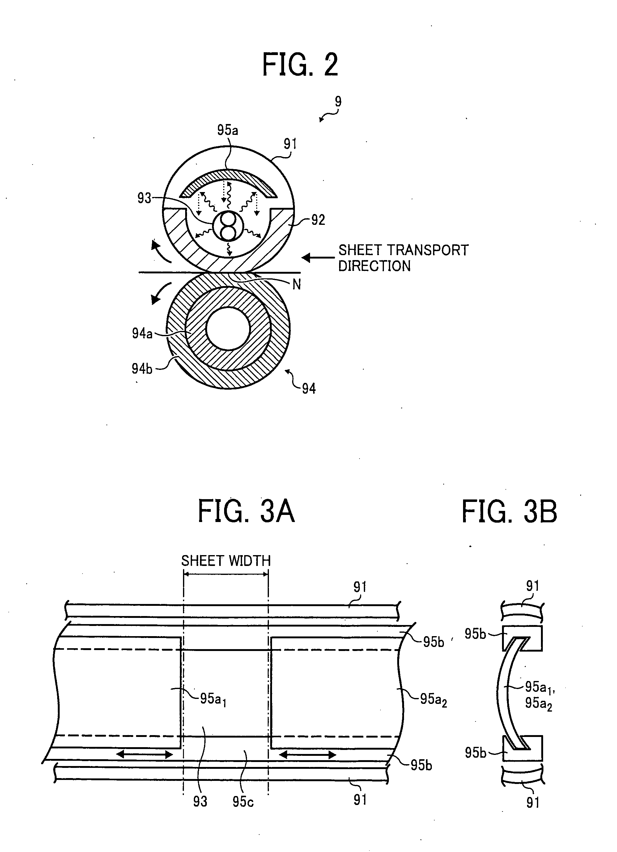
A fixing unit includes a fixing member, a pressing member, a heating device, a sheet width detector, and a heating area adjustor. The pressing member faces the fixing member to form a fixing nip between the fixing member. An un-fixed toner image is fixed on a recording medium when the recording medium passes through the fixing nip. The heating device heats the fixing member while maintaining a non-contact condition with the fixing member. The sheet width detector detects sheet width of the recording medium. The heating area adjustor changes a heating area of the fixing member, heatable by the heating device, based on the sheet width detected by the sheet width detector. The heating area adjustor is moveable in a space between the fixing member and the heating device along a sheet width direction to change a size of the heating area.

Description

CROSS-REFERENCE TO RELATED APPLICATIONS[0001]This application claims priority to Japanese Patent Application No. 2008-233550, filed on Sep. 11, 2008, in the Japan Patent Office, the entire contents of which are hereby incorporated by reference herein.BACKGROUND OF THE INVENTION[0002]1. Field of the Invention[0003]The present invention relates to an image forming apparatus employing a fixing unit for fixing a toner image transferred onto a recording medium (e.g., transfer sheet).[0004]2. Description of the Background Art[0005]Typically, image forming apparatuses using electrophotography employ a fixing unit using heat and pressure to fix images on recording media. The fixing unit include a fixing belt having a heat source therein and a pressure roller, with the fixing belt and the pressure roller forming a pressing portion (or nip portion) therebetween. When a transfer sheet having an un-fixed toner image thereon passes the nip portion, the fixing belt and the pressure roller apply h...

Claims


Application Information

Patent Timeline
Patent Type & Authority Applications(United States)
IPC IPC(8): G03G15/00
CPCG03G15/2042G03G2215/00734
Inventor SEKI, TAKAYUKI
Owner RICOH KK
Learn More