Hole saw assembly including drive shafts supported by a rotatable annulus

a technology of drive shaft and annulus, which is applied in the direction of sleeve/socket joint, sawing apparatus, turning apparatus, etc., can solve the problems of difficult removal of plugs, tight plugs, and considerable force to be used to remove plugs

Active Publication Date: 2010-03-18
KEIGHTLEY KYM JOHN
View PDF38 Cites 46 Cited by
  • Summary
  • Abstract
  • Description
  • Claims
  • Application Information

AI Technical Summary

Benefits of technology

[0015]Preferably said base forms part of the hole-saw body which when connected to the mandrel is prevented from rotational motion relative thereto.
[0016]Alternatively said base is in the form of a locking ring which when attached to the mandrel is prevented from rotational motion relative thereto, said locking ring including an attachment means for attaching one or more hole-saws thereto.

Problems solved by technology

A universal problem when using hole-saws is that when a hole has been drilled through a material, the material that has been cut out, commonly referred to as the plug, remains embedded within the hole-saw and needs to be removed.
Typically the plug is jammed tightly within the hole-saw and considerable force needs to be used to remove the plug using a sharp instrument, such as a screwdriver.
However, some materials, such as plastic, possess material characteristics that make their removal difficult.
Whilst some of these have been found to work well, they are generally mechanically quite complicated.
Further, the hole-saw is a dedicated size being limited to a pre-determined diameter and to drill larger size holes requires the use of a whole new hole-saw assembly.

Method used


Image

  • Hole saw assembly including drive shafts supported by a rotatable annulus
  • Hole saw assembly including drive shafts supported by a rotatable annulus
  • Hole saw assembly including drive shafts supported by a rotatable annulus

Examples


second embodiment

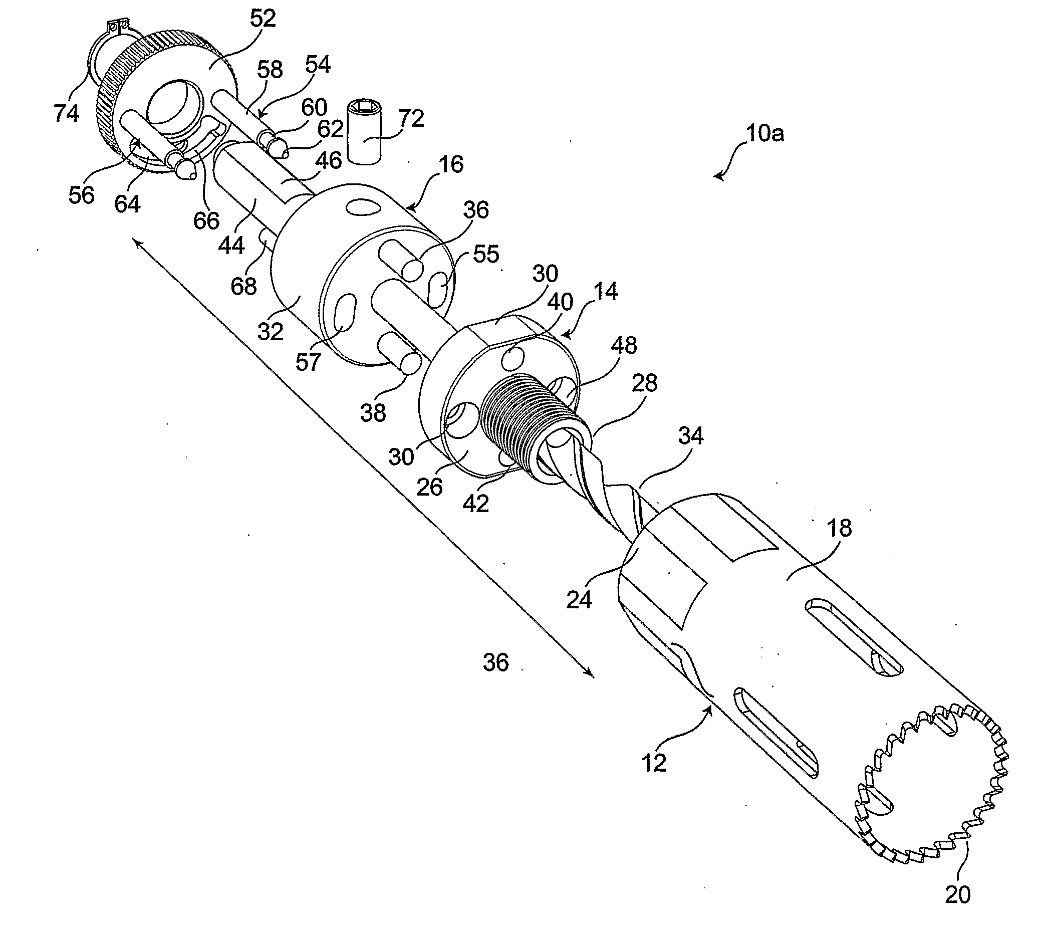
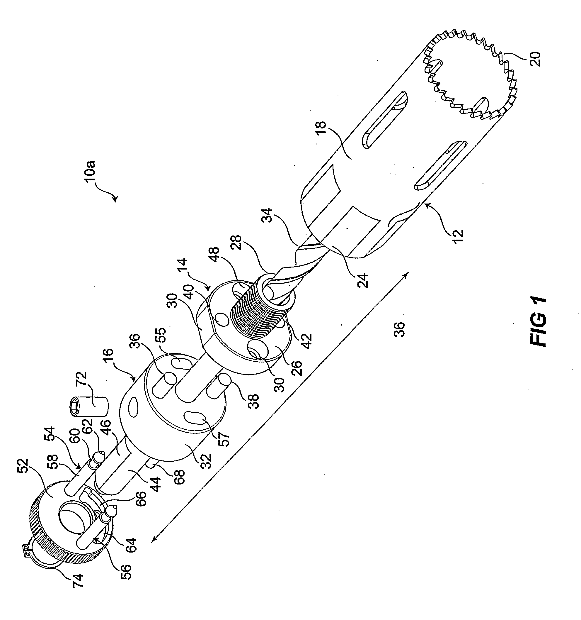
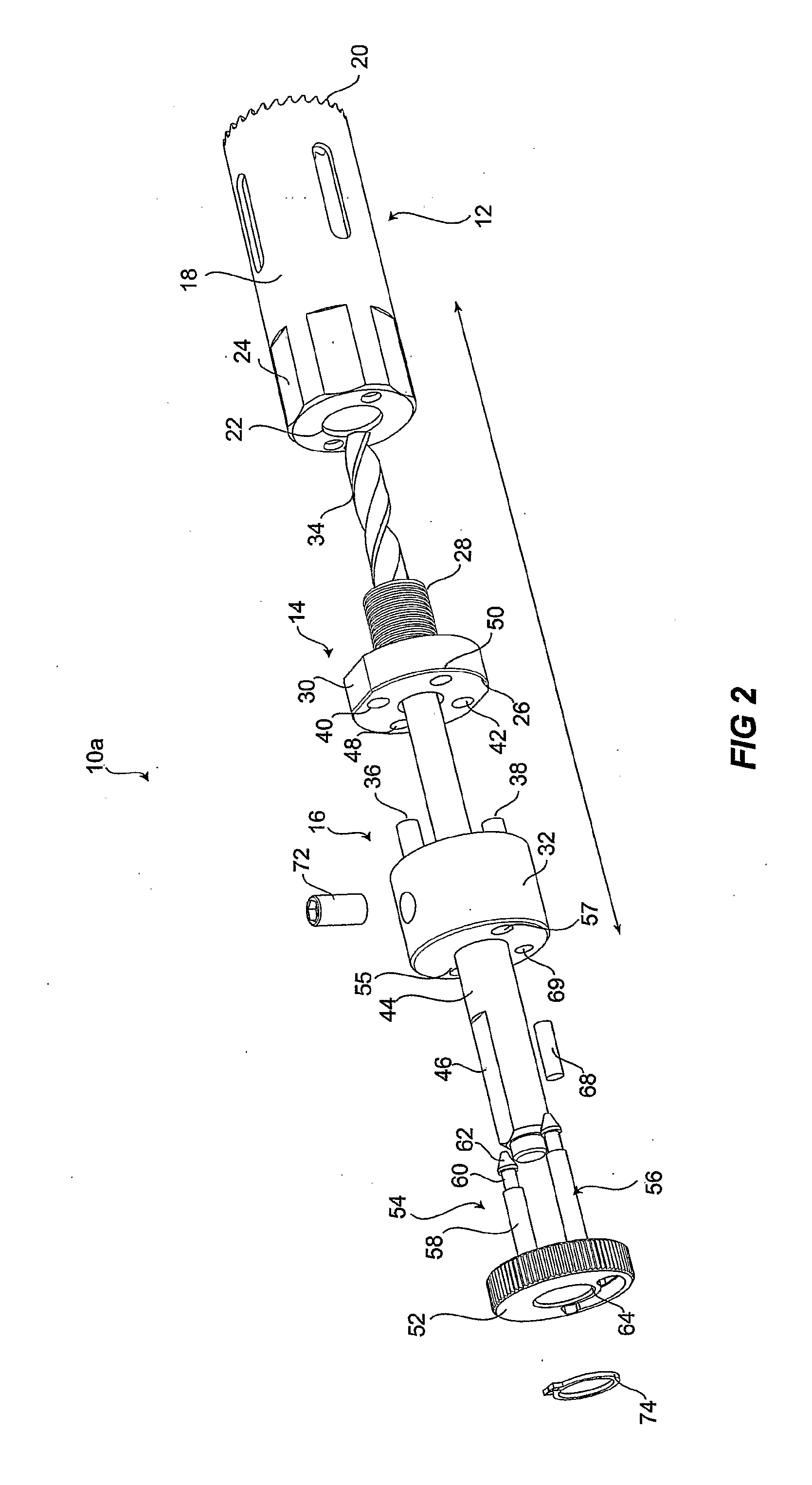
[0052]Turning now to the present invention illustrated in FIGS. 7-12, where there is shown a hole-saw assembly 10b in which the hole-saw 12 is directly lockable to the mandrel body 16 without the need for a base / locking ring. It is to be understood that like parts are referred to using like numbers and may not be described again.

[0053]The co-axial annulus or ring 76 is similar to that previously described in that it is rotatably movable with respect to the mandrel body 78 between a first and a second position. The shafts 80 and 82 extend from the same position and in the same direction and again, only shaft 80 will be described in the following paragraphs given that shaft 82 is identical.

first embodiment

[0054]Shaft 80 includes a column 84 having a smaller diameter to that of shaft 54 of the The diameter is approximately equivalent to that of the flute 60 in assembly 10a. So in the present embodiment there is effectively no longer a flute portion, just a thin column 84 terminating in a chamfered cap 86. The benefit of having a column of this size and shape is so that elliptical apertures do not need to be drilled into the mandrel body 78. The circular apertures 88 and 90 in the mandrel body 78 are therefore positioned and sized to allow for the insertion, passage through, and rotation of the respect shafts 80 and 82 between the first and second positions. The diameter of each aperture is slightly larger than the chamfered caps.

[0055]Those skilled in the art would realize the cost and time benefits in having circular apertures 88 and 90 as opposed to the elliptical apertures proposed in assembly 10a which require skilled machining of the mandrel 16.

[0056]Extending alongside and in t...


PUM

PropertyMeasurementUnit
diameteraaaaaaaaaa
thicknessaaaaaaaaaa
diametersaaaaaaaaaa

Abstract

A hole-saw assembly including a hole-saw having at one end a plurality of cutting teeth and at the other end a base having two holes therethrough. two shafts. The assembly includes a mandrel coaxially aligned with said hole-saw and including a body having two bores therethrough, and an annulus located on top of the body which is coaxially aligned with said mandrel and hole saw. The annulus includes two shafts co-axial with the mandrel bores, and is rotatable around its longitudinal axis from a first to a second position. In the first position the annulus shafts are aligned with the base holes allowing the shafts to be freely insertable and removable and in the second position the shafts are misaligned to lock the shafts to the base. In one embodiment the mandrel bores are shaped to accommodate rotation of the shafts, and in a further embodiment, the shafts are configures to rotate within circular mandrel bores. Such an arrangement allows the hole-saw and the mandrel to be easily and quickly mountable and demountable.

Description

BACKGROUND OF THE INVENTION[0001]The present invention relates to a hole-saw assembly or arrangement and in particular to a hole-saw with a base that is easily demountable and mountable from a mandrel engageable by a drill.[0002]Hole-saws are a very widely used tool for many applications. Typically a hole-saw includes a flat solid base that is locked by a drill, the base providing support for the hole-saw. Some bases include multiple diameter grooves adapted to accommodate hole-saws of different diameters. Yet others are single sized hole-saws.[0003]A universal problem when using hole-saws is that when a hole has been drilled through a material, the material that has been cut out, commonly referred to as the plug, remains embedded within the hole-saw and needs to be removed. Typically the plug is jammed tightly within the hole-saw and considerable force needs to be used to remove the plug using a sharp instrument, such as a screwdriver. However, some materials, such as plastic, poss...

Claims


Application Information

Patent Timeline
Patent Type & Authority Applications(United States)
IPC IPC(8): B23B51/04B26D7/18
CPCB23B51/0426B23B51/0473B27B5/12B27B5/32Y10T408/96Y10T408/8973Y10T408/95Y10T408/895Y10T408/51Y10T279/16
Inventor KEIGHTLEY, KYM JOHN
Owner KEIGHTLEY KYM JOHN
Why Eureka
Try Eureka