Remotely controlled robots having improved tool deployment systems

a robot and remote control technology, applied in the field of remote control robots, can solve the problems of wasting valuable time and resources, unable to change the tooling attached to the gripper, and more difficult to complete hazardous material operations, etc., to achieve the effect of saving battery power, reducing labor intensity and limited operation

Inactive Publication Date: 2010-03-18
AGENS MICHAEL W
View PDF6 Cites 84 Cited by
  • Summary
  • Abstract
  • Description
  • Claims
  • Application Information

AI Technical Summary

Benefits of technology

[0017]Although the present invention is not limited by any particular theory of operation, it is well known to those skilled in the art that remote controlled robots may have an on-board battery supply having a limited operational life that requires frequent recharging. Thus, the present invention addresses this power issue by bringing a plurality of tools downrange in the tool basket. As a result, the robot does not have to return up range to change tools, which makes the robot more versatile and saves battery power so that the robot will be less likely to run out of battery power.

Problems solved by technology

Because the tools are attached to the outside of the gripper fingers, the tools are not centered upon the gripper, which makes it more difficult to complete a hazardous material operation.
As a result, the tooling attached to the gripper may not be changed when the robot is located downrange.
Rather, the robot must be brought back up range in order to change the tools attached to the gripper, which wastes valuable time and resources.

Method used


Image

  • Remotely controlled robots having improved tool deployment systems
  • Remotely controlled robots having improved tool deployment systems
  • Remotely controlled robots having improved tool deployment systems

Examples


Embodiment Construction

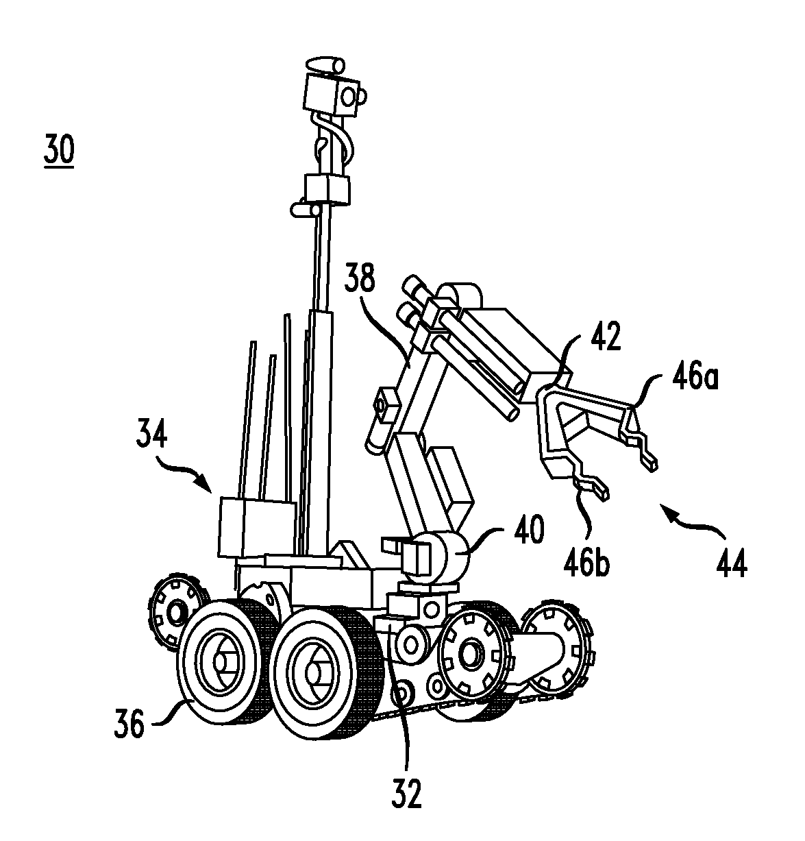
[0042]FIG. 1 shows a remote controlled robot 30 that is used for detecting, defusing, and disposing of explosive devices. The remote controlled robot 30 includes a platform 32 that supports equipment 34 and a plurality of wheels 36 for maneuvering the robot 30. A leading end of the platform 32 has an articulating arm 38 mounted thereon. The articulating arm 38 includes articulating joints 40 that enable the arm 38 to move in different directions for engaging objects. A distal end 42 of the articulating arm 38 includes a gripper 44 having a first gripper finger 46A and second gripper finger 46B that oppose one another. The gripper fingers 46A, 46B open and close toward one another for releasing and grasping objects.

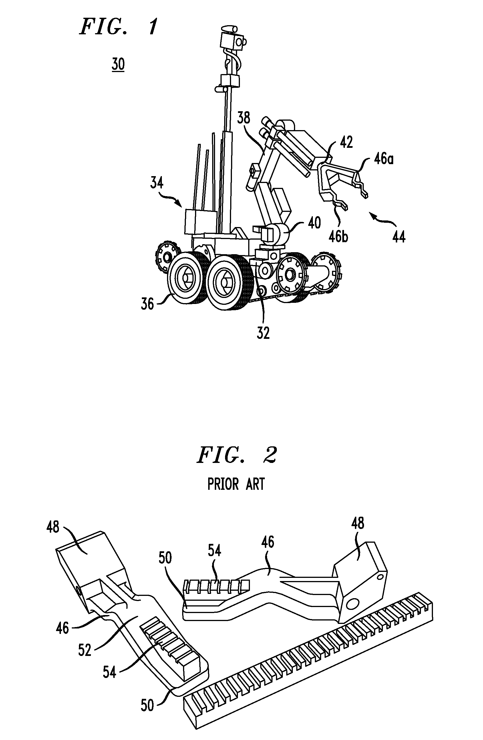
[0043]FIG. 2 shows a pair of gripper fingers 46 before being assembled to the distal end of an articulating arm of a remote controlled robot. The gripper fingers 46 has proximal ends 48 that are secured to the distal end of the articulating arm of the remote controlled rob...


PUM


Abstract

A remote controlled robot for handling hazardous material, such as explosive devices, includes a support frame, an articulating arm having a proximal end coupled with the support frame and a distal end remote therefrom, and a gripper connected with the distal end of the articulating arm, the gripper having gripper fingers that oppose one another. The robot includes a transporting assembly, such as wheels or a track, coupled with the support frame for selectively moving the robot to a desired location. The robot includes a tool basket disposed adjacent the proximal end of the articulating arm. The tool basket includes a plurality of tool receiving slots adapted to receive tools, with different tools stored in each of the slots. By carrying a plurality of tools in a basket, the robot may stay downrange when changing tools, rather than requiring the robot to return up range for changing tools.

Description

BACKGROUND OF THE INVENTION[0001]1. Field of the Invention[0002]The present invention generally relates to remotely controlled robots, and more specifically relates to remotely controlled robots used to detect, disable, and dispose of explosive devices, as well as vehicle entry, structure entry, surveillance, and barricaded subjects.[0003]2. Description of the Related Art[0004]Remote controlled robots are used by the military and public safety organizations to detect, defuse and dispose of hazardous materials such as explosive devices, and when addressing various hazardous incidents. Typically, these remote controlled robots include wheels or tracks that carry the robot to the site of a hazardous condition. Many of these remote controlled robots include an articulating arm with a gripper located at the distal end of the arm. The gripper includes opposing gripper fingers that move toward one another for closing the gripper and away from one another for opening the gripper.[0005]Remot...

Claims


Application Information

Patent Timeline
Patent Type & Authority Applications(United States)
IPC IPC(8): B66C3/00
CPCB66C3/18F41H11/28F41H11/16B25J11/0025B25J15/04
Inventor AGENS, MICHAEL W.
Owner AGENS MICHAEL W
Why Eureka
Try Eureka