Measuring device, in particular vectorial network analyzer, with separate oscillators

a technology of vector network analysis and measuring device, applied in the direction of measurement device, frequency measurement arrangement, instruments, etc., can solve the problems of reducing the time of measuring, reducing the operational life of the switch matrix, and affecting the accuracy of the signal

Active Publication Date: 2005-11-29
ROHDE & SCHWARZ GMBH & CO KG
View PDF11 Cites 22 Cited by
  • Summary
  • Abstract
  • Description
  • Claims
  • Application Information

AI Technical Summary

Benefits of technology

[0007]In accord with the invention, each excitation / receiving unit has at least one own oscillator, separate from the signal generator, which produces the oscillator signal for the mixer of the receiving apparatus dedicated to this excitation / receiving unit. With this arrangement, the frequency and / or the phase of the oscillator-signal is adjustable independently of the frequency and / or the phase of the oscillator signal of the oscillators of the other excitation / receiving units. Thereby, it becomes possible, to operate the receiving apparatuses of the different excitation / receiving units with different intermediate frequencies. This has, as will be explained in greater detail with the aid of FIGS. 1 and 3 the advantage that the image-frequency problem and the sum-frequency problem can be resolved.

Problems solved by technology

In any case, with the switch matrix, in addition, there is always required a switching isolation of some 140 dB, which itself is of some cost.
Beyond this, the operational life of the switch matrix is limited by the use of mechanical switches.
Further, mechanical switches, because of their relatively long switching time clearly reduce the time of measuring.
By the use of electronic switches, then the problem of a deterioration of the signal quality and a debilitation of the measuring dynamics arises.

Method used


Image

  • Measuring device, in particular vectorial network analyzer, with separate oscillators
  • Measuring device, in particular vectorial network analyzer, with separate oscillators
  • Measuring device, in particular vectorial network analyzer, with separate oscillators

Examples


Embodiment Construction

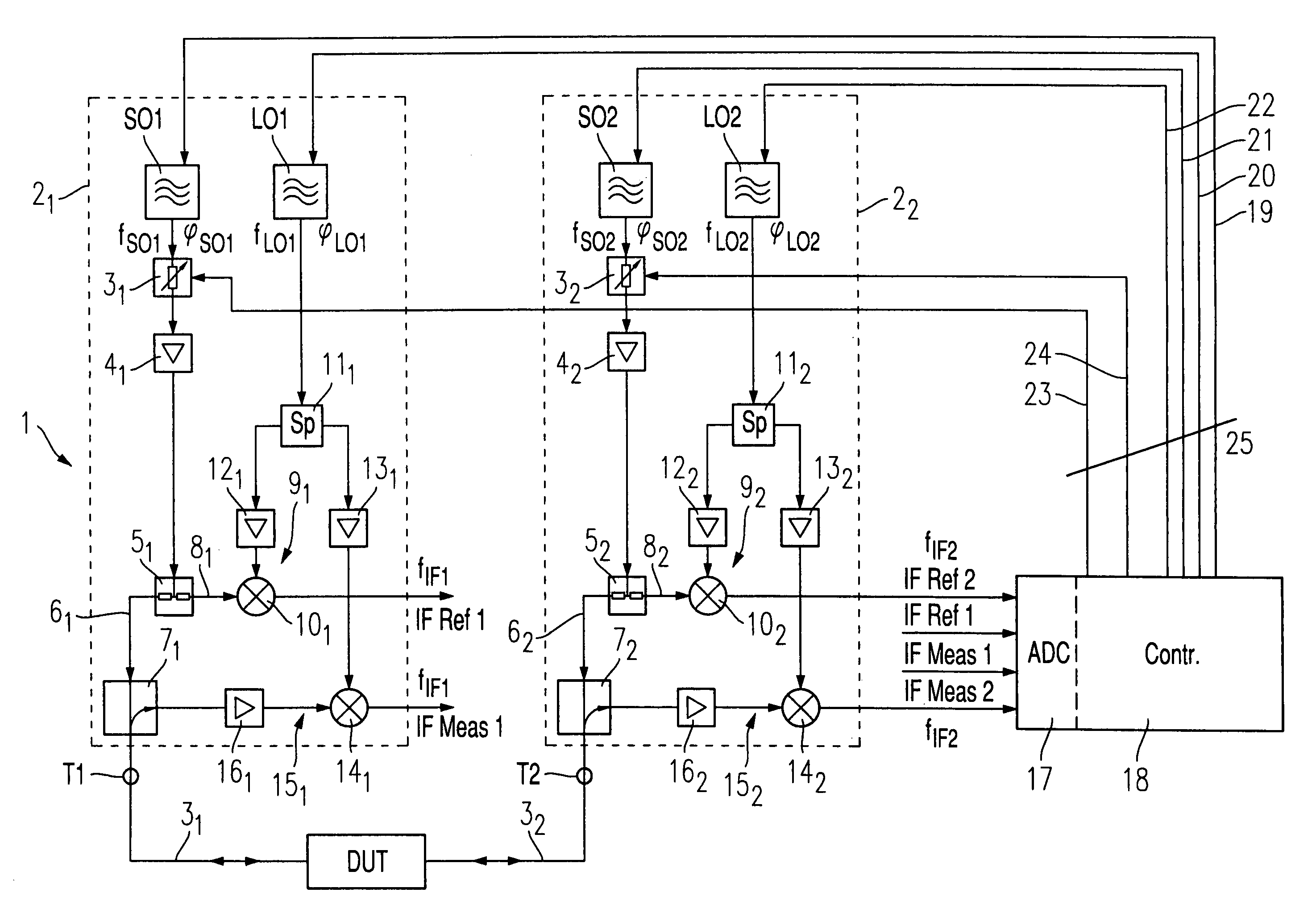
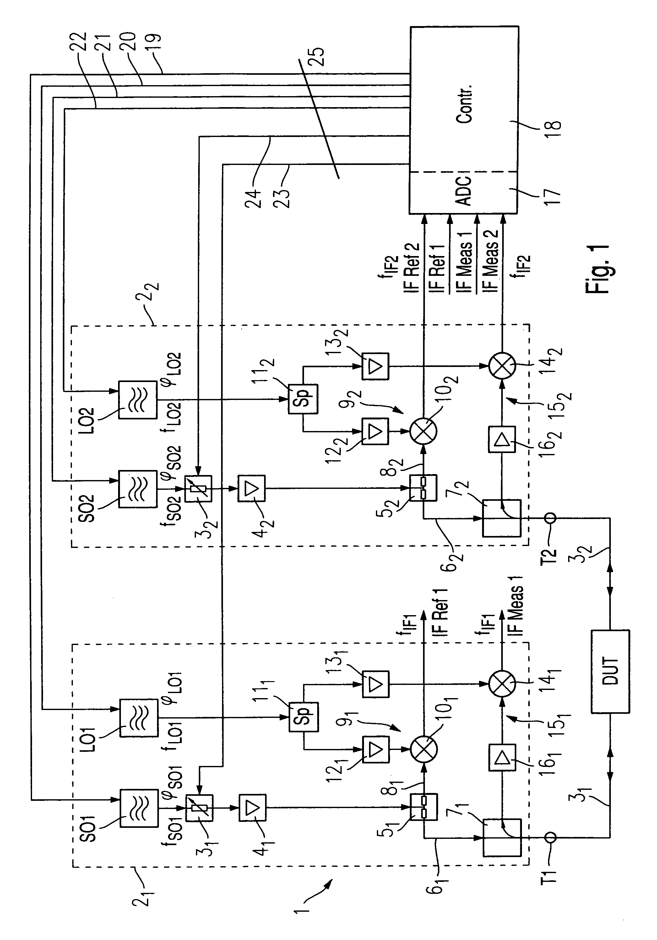
[0015]FIG. 1 shows an embodiment example of the invented measuring device 1. In the illustrated embodiment, the presentation of a measuring device concerns a vectorial network analyzer. The invented measuring device 1, however, is not limited to application on a network analyzer. Further, what is shown is an embodiment of a 2-port network analyzer. Mention should be made here, that the inventive concept, in the case of vectorial network analyzers is not limited to 2-port network analyzers, but is valid especially where multi-port network analyzers with more than 2-measuring ports is concerned.

[0016]In accord with the concept of the invention each port T1, T2 of the measurement device 1, is provided with a separate excitation / receiving unit 21,22. Each excitation / receiving unit 21, 22 has a signal generator SO1, SO2, by means of which the device under test DUT can be served with an excitation signal. Either only one of the two signal generators SO1, SO2 can be activated, or even both...


PUM


Abstract

A measuring device (e.g., a vectorial network analyzer) by means of at least two ports can be connected to a device under test and has associated excitation/receiving units (ERUs), each thereof having one port. At least one ERU has a signal generator, which can apply an excitation signal onto a device under test. Each ERU possesses two receiving apparatuses (each with a mixer in connection with an oscillator signal) to receive the excitation signal, the reflected signal from the associated port or the signal transmitted to the associated port and converts said signal into an intermediate signal. Each ERU exhibits its own oscillator separate from the signal generator, and generates the oscillator signal for the mixer of the receiving apparatus of the ERU, whereby the frequency and/or phase of the oscillator signals, can be adjusted independently of the frequency and/or phase of oscillator signals of the oscillators of other ERUs.

Description

BACKGROUND OF THE INVENTION[0001]The invention concerns a measuring device, especially a vectorial network analyzer. Network analyzers serve for the characterization of a device under test by the measurement of wave values, especially of S-parameters.[0002]If the device under test is, for instance, a 2-port device, then, in a forward measurement, the wave which is projected toward a first port of the device under test, the reflected wave from the first port of the said device under test, as well as the wave which is transmitted through the device under test and exits at the second port, i.e., a forward transmitted wave, are measured. In a reverse measurement, the wave moving toward the second port of the device under test, the wave reflected from the second port as well as the wave transmitted through the device under test and emerging from the first port, i.e. backward-transmitted, are measured. From these measured wave values, various parameters may be computed, for instance, the ...

Claims


Application Information

Patent Timeline
Patent Type & Authority Patents(United States)
IPC IPC(8): G01R23/14G01R23/173G01R27/28
CPCG01R23/14G01R27/28
Inventor EVERS, CHRISTIANKRAUS, PETERBOSS, HERMANN
Owner ROHDE & SCHWARZ GMBH & CO KG
Why Eureka
Try Eureka